Opensource Arduino Mega 2560 Smart Home Controller with MQTT, DMX-512, 1-Wire, Modbus and Openhab Support
 Today I decided to submit to the public a draft project, which I had been working on for the last couple of years: LightHub . What came out as a result can be called, perhaps, the cheapest solution for creating a Smart Home, which, nevertheless, can:
- Control lighting and power devices (Relays, DMX-512 and Modbus RTU dimmers)
- Manage warm floors (as many as a dozen cheap DS18B20, divorced around the apartment) are used as thermal sensors
- Control ventilation / air conditioning valves
- Manage a homemade ventilation system.
- Much of this, which I initially did not think about, simply due to the fact that the controller turned out to be absolutely open, flexibly configurable, and perfectly complementary Open-Sourcing Solutions Openhab + Mosquitto + NodeRed
Conventional switches, buttons, contact sensors, leakage sensors, etc. are connected to the controller. They can control both local loads and devices connected to other such controllers or to everything that the MQTT protocol understands. I, for example, have a reed switch mounted in the front door box. When I close the lock on three turns - turn off the light, heated floors, boilers, AV receiver. When I return, the condition of these devices is restored as it was before leaving.
On the way out, for example, there are such relay modules , DMX, Modbus peripherals.
The controllers are configured using JSON files, which when the controller is started are loaded via http (hereinafter, the config can be saved to NVRAM via the Serial CLI). And, of course, all this is controlled by the system Openhab 2, through a regular mobile application.
The tasks of “small automation” are solved both with the help of standard openhab rules (not very convenient), and with the help of NodeRed. (Regarding NodeRed, here is an article that perfectly describes an example of automation.)
Sources, along with examples of configs, are uploaded to GIThub , a bit of a description I post on the project website. Accordingly, a more complete story under the cut.
UPDATE: Six months have passed since the publication and the industrial prototype of the device looks like this during installation in an electrical cabinet. 
Arduino DUE board installed on the motherboard.
The card is removed, visible optical decoupling, protection of inputs, drivers DMX, Modbus, 1-wire, powerful transistor assembly (for example) to control the relay.

And this is how the controller looks like on a DIN rail (the cover is removed), next to the typical relay block. (As I wrote, I deliberately do not put the power elements inside the controller housing)
Arduino DUE board installed on the motherboard.
The card is removed, visible optical decoupling, protection of inputs, drivers DMX, Modbus, 1-wire, powerful transistor assembly (for example) to control the relay.
And this is how the controller looks like on a DIN rail (the cover is removed), next to the typical relay block. (As I wrote, I deliberately do not put the power elements inside the controller housing)
It all started with the repair in the apartment, during which I decided to make the house decently smarter.
At the same time, frankly, we didn’t want to spend serious money on the “Brand” solution of the Smart Home. Moreover, many “Serious” solutions used closed standards and integrated with each other with the help of overt crutches.
Accordingly, I set myself the task of assembling the Smart Home from the most ready and inexpensive components.
As the Hardware for the controller, I chose the Arduino Mega 2560 + Ethernet shield.
Update: Having listened to the comments below, I ported the project to the Atmel SAM3X8E ARM Cortex-M3 (Arduino DUE), the board, which at the same cost of a penny, has an order of magnitude greater performance, and most importantly - RAM. We had to tinker with the DMX library, but now both DMX-IN and DMX-OUT work using the same hardware USART, without taking up processor resources. The project already lies on github and is compiled automatically under the necessary platform.
A cheap price, a huge number of input / output ports, 4 hardware UARTs, a decent size of NVRAM, which I have so far managed to occupy only 30% with firmware and which fits with the entire config, and, right in JSON format, they confirmed the reasonableness of the choice.
After updating the Bootloader, and adjusting the Ethernet library, we managed to successfully use the hardware Watchdog of the processor, which added to the “industry” solution, and I still have peace of mind, although the firmware was not seen to hang without it.
The absence of any operating system on the controller allows it to be considered a “real-time system”, which allows, for example, to programmatically generate the same DMX signal.
The bottleneck is the size of the RAM. And it does not allow to use all the immense periphery of the controller. Although, more than 30 different channels (items, in terms of the config) keep in memory quite well. And to connect as much as the Arduino Mega board allows is, nevertheless, a task unrelated to reality.
(on ARM - no more than this bottleneck)
Also, scalability is achieved by increasing the number of devices. For example, I have two controllers involved. They are spaced around the apartment (this, too, allows you not to pull all the wires into one point). To interact with each other, as well as with the systems Openhab and NodeRed, MQTT broker Mosquitto is used.
As a 1-wire bus driver, I used a chip (I2C driver) ds2482-100 with Aliexpress , which at a price of 60 rubles ensures stable operation with a bus up to 100M.
For flexible configuration of the device, I modified the AJSON library for Arduino so that it has the ability to both download the object via http and read and write the object from / to the NVRAM controller. Fork is available on Github .
Serial CLI when creating a new controller, you need to register a unique MAC address in NVRAM. It is MAC that is the key by which the c http server configuration is initially loaded.
As a management software, I took Openhab 2, which has all the functionality I need, plus a mobile application, plus Cloud, whose role, however, is only to provide access to the home infrastructure from the outside, without pushing ports on the router and not possessing fixed IP. Also, Openhab has integration with Apple's HomeKit, which allows you to control devices at home from the iPhone, without installing the application at all. (The opportunity is interesting, but I mostly use the “native” application).
Some screenshots of Openhab 
The presence in the project of the apartment a large number of LED lighting, also required some kind of reasonable management.
Details on LED lighting
The solutions found on the market were either closed "things in themselves" or cost inadequate money while supporting few channels. Often, manufacturers were limited to three channels (RGB), although the RGBW variant allows the use of LED tapes as the main illumination, and not just for the color backlight.
Thinking, I ordered a couple of boards on the AliExpress, each of which can control 30 LED channels with a rated current up to 2A per channel.
In order to increase the maximum power of one channel, I switched from LED strips to 12V to 24V tapes. At the same time, fully illuminate the room about 16-18 square meters. m was possible with the help of 4 keys. Larger areas had to be zoned - in the living room, independently connected 4 tapes of 5 m each, using 16 channels.
For synchronous control of the entire room, I had to think of a channel type “group”
Here is the description of the living room in the JSON config:
The first element of the array is the channel type, the second is the channel parameter, which can be an array.
For an element of type 7 (group) - the argument is an array of elements included in the group.
Recursion, of course, is supported.
For an item of type 1 (RGBW tape), the argument is the base DMX channel address.
With the standard EasyDMX library, the boards did not work right away. As it turned out, the Chinese LED controller did not digest 2ms delay between DMX frames (interframe delay). A simple modification of the library code (halving the cycle) helped.
Fork library on github
At the request of readers, added pictures on the topic "LED lighting into action"
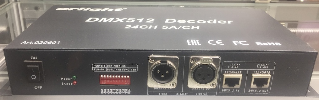
This is an alternative DMX decoder from the “expensive and rich” category.
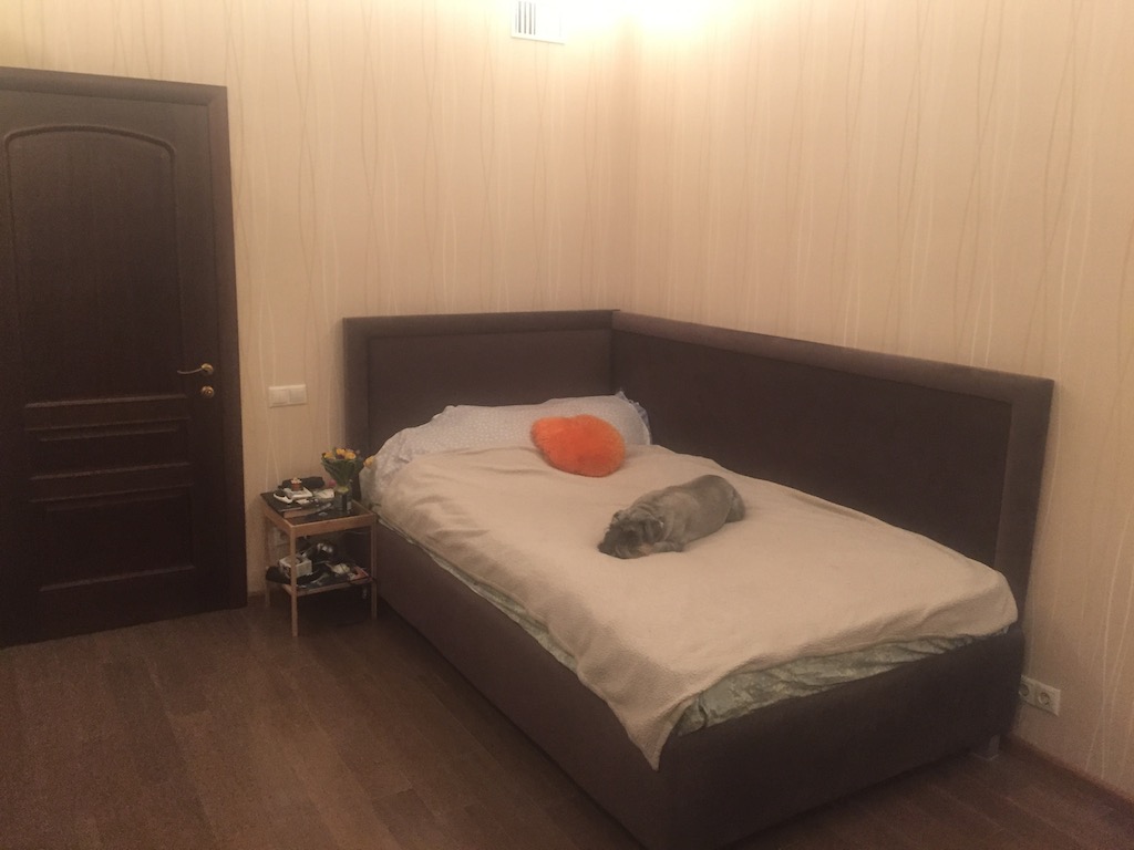
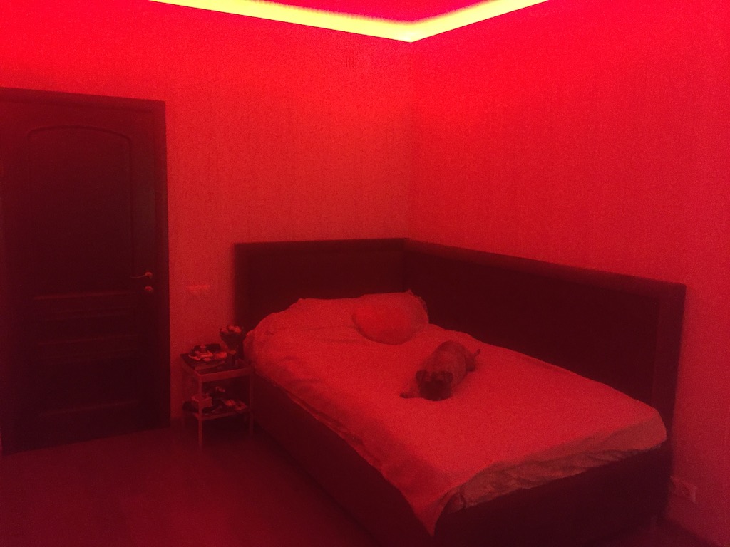
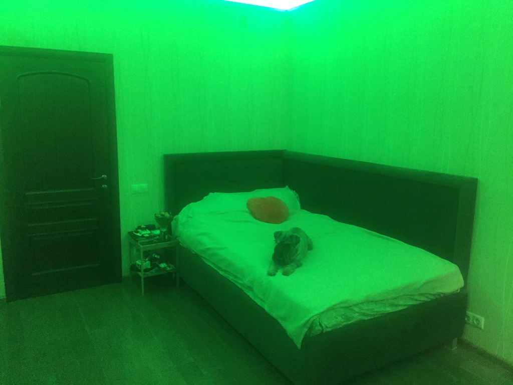
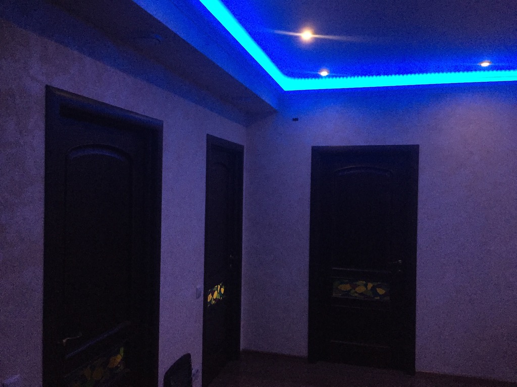
Further, the “photo session”, where you can understand how much the rooms change when the lighting changes, and also that using only white color in RGBW tapes, you can get a scattered lighting that is pleasing to the eye.
I recommend tapes exclusively with warm white light (2700K)


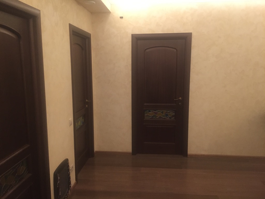
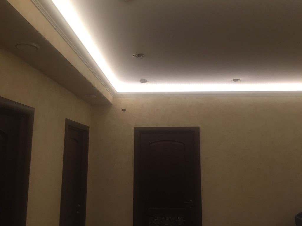
And then, some examples of combining spotlights and LEDs:


Thinking, I ordered a couple of boards on the AliExpress, each of which can control 30 LED channels with a rated current up to 2A per channel.
In order to increase the maximum power of one channel, I switched from LED strips to 12V to 24V tapes. At the same time, fully illuminate the room about 16-18 square meters. m was possible with the help of 4 keys. Larger areas had to be zoned - in the living room, independently connected 4 tapes of 5 m each, using 16 channels.
For synchronous control of the entire room, I had to think of a channel type “group”
Here is the description of the living room in the JSON config:
"kuh":[7,["kuhline","kuhfre","kuhwork","kuhwin"]], "kuhwin":[1,5], "kuhline":[1,13], "kuhfre":[1,25], "kuhwork":[1,1],
The first element of the array is the channel type, the second is the channel parameter, which can be an array.
For an element of type 7 (group) - the argument is an array of elements included in the group.
Recursion, of course, is supported.
For an item of type 1 (RGBW tape), the argument is the base DMX channel address.
With the standard EasyDMX library, the boards did not work right away. As it turned out, the Chinese LED controller did not digest 2ms delay between DMX frames (interframe delay). A simple modification of the library code (halving the cycle) helped.
Fork library on github
At the request of readers, added pictures on the topic "LED lighting into action"
This is an alternative DMX decoder from the “expensive and rich” category.
Further, the “photo session”, where you can understand how much the rooms change when the lighting changes, and also that using only white color in RGBW tapes, you can get a scattered lighting that is pleasing to the eye.
I recommend tapes exclusively with warm white light (2700K)
And then, some examples of combining spotlights and LEDs:
Normal AC 220V lighting I managed to control Chinese dimmers with Aliexpress that have support for Modbus RTU (standard industrial control protocol over RS-485). These dimmers are perfectly controlled locally (by switches without latching), at the same time, the controller has the ability to read the brightness and control them via the Modbus bus (implemented for now for a two-channel device).
At the time of publication of the article, the dimmers were gone from Aliexpress, but I found a Chinese manufacturer by label on the printed circuit board of the device. Here is a link to their ascetic site . E-mail questions are answered willingly, they even sent short documentation.
Another option for controlling 220V lighting is to use a DMX-512 AC dimmer. On e-bay such in the range, any form factor - board or DIN rail. From one to eight channels.
At the beginning, I was careful of this option, since the controller was still in a very experimental way and, for reliability, I wanted to maintain autonomous local control. But now I would use this option.
Next - I installed a channel air conditioner, which is able to both heat and cool the entire apartment. In order to somehow distribute the cold and warmth in the bedrooms, I installed servos with a 0-10V signal control. The opening angle of the gate valves is adjusted automatically with the help of NodeRed, in which a convenient PID controller was found for this.
Details on air conditioning
Unfortunately, it was not possible to find air damper drives with PWM or some kind of digital input, so on the same AliExpress 4 PWM converters to a standard 0..10V analog signal were purchased.
Unfortunately, I don’t see these devices on Aliexpress, but on e-bay - please
The transducers made great money right away; I just had to reprogram the PWM output timer in order to set the appropriate frequency.
Below is an example of reprogramming timers 3 and 4 (they are responsible for pin 2, 3, 5, 6, 7, 8 Arduino Mega at a frequency of 4000 Hz).
pinMode(iaddr,OUTPUT); //timer 0 for pin 13 and 4 //timer 1 for pin 12 and 11 //timer 2 for pin 10 and 9 //timer 3 for pin 5 and 3 and 2 //timer 4 for pin 8 and 7 and 6 int tval = 7; // 111 in binary - used as an eraser TCCR4B &= ~tval; // set the three bits in TCCR2B to 0 TCCR3B &= ~tval; tval=2; //prescaler = 2 ---> PWM frequency is 4000 Hz TCCR4B|=tval; TCCR3B|=tval; analogWrite(iaddr,k=map(Value,0,100,0,255));
Next, I started looking for WiFi controllers for underfloor heating. I found, in general, a good device worth about 6 thousand rubles from Teplolux, but it had some significant drawbacks for me.
Despite the presence of a mobile application, the control protocol was closed. I did some reverse engineering, which showed that, theoretically, the protocol could be decrypted. Perhaps I would have done this, but I found that without reinstalling the subcontractors, this device is not installed in the same row as the switches. This determined the fate of the device: having sold it, I implemented the functionality of a simple thermostat on my controller, saving almost 30 thousand rubles on 5 warm floors.
It turned out the following:
Here is an example of a config for one warm floor:
When polling the OneWire thermometer with the specified address, the data is transmitted to the MQTT bus in the t_bath1 topic, and also, inside the controller, to the h_bath object of type No. 5 (thermostat), the relay is connected to the controller pin # 24, the setpoint is 33 degrees (can be corrected by MQTT )
- All management - locally on the controller and independent of the home IT infrastructure
- Measurements from 1-wire thermal sensors are used. If the sensor cannot be interrogated for a long time, the heater is turned off.
- Through MQTT you can turn on / off the warm floor and set its temperature. Accordingly, the floors are managed through the interfaces and the mobile app Openhab.
- I did not implement tricky scripts and schedules on the controller. If desired, this is easily implemented by the rules of Openhab or Node-Red. I limited myself to turning off devices when people leave the house.
Here is an example of a config for one warm floor:
"ow":{ "2807FFD503000036":{"emit":"t_bath1","item":"h_bath1"} }, "items":{ "h_bath1":[5,24,33], },
When polling the OneWire thermometer with the specified address, the data is transmitted to the MQTT bus in the t_bath1 topic, and also, inside the controller, to the h_bath object of type No. 5 (thermostat), the relay is connected to the controller pin # 24, the setpoint is 33 degrees (can be corrected by MQTT )
Device inputs
In the config for each input, you can specify how to send a command to a local object or issue a command to the MQTT topic. And, separately, both on the conditional “pressing” of the button and on the “release”.
Examples:
Pin 41: Reed switch on the front door lock - when locked - issue the HALT command to the topic / myhome / in / all, when unlocking - the REST command.
In my case, this leads to a complete “falling asleep” and “waking up” at home. By the way - the commands are not included in the standard set of OpenHab, but it turned out extremely convenient - HALT - turns off the device, REST - restores the device's parameters to the last value (color, brightness, temperature), but only for the device that was turned off with the HALT command and not OFF. This allows you to not include what was turned off at the time of leaving the house.
Pin 38: Just an ordinary light switch. On closure, it issues (by default) the ON command, on opening, the OFF command. These values are passed to the spots_en object. It is clear that the state of the object can be changed from a mobile application. In this case, the switch, as it were, remains, for example, in the on position, but the light is turned off.
For lovers of classic circuit-breakers, the syntax of Pin 40 fits: When turned on and turned off, a TOGGLE command is issued (also, incidentally, a new, relatively OpenHab) device that changes the On-Off position of the device (in this example, the lamp is controlled not locally, but through MQTT another controller).
If this is not a toggle switch and a button, it is enough just to correct “rcmd”: "" - the switching command will be issued only when pressed.
"in":{ "41":{"emit":"/myhome/in/all","scmd":"HALT","rcmd":"REST"}, "38":{"item":"spots_en"}, "37":{"emit":"/myhome/in/light","scmd":"ON","rcmd":"OFF"}, "40":{"emit":"/myhome/in/gstall","scmd":"TOGGLE","rcmd":"TOGGLE"}, "35":{"emit":"/myhome/s_out/water_leak"} }
Pin 41: Reed switch on the front door lock - when locked - issue the HALT command to the topic / myhome / in / all, when unlocking - the REST command.
In my case, this leads to a complete “falling asleep” and “waking up” at home. By the way - the commands are not included in the standard set of OpenHab, but it turned out extremely convenient - HALT - turns off the device, REST - restores the device's parameters to the last value (color, brightness, temperature), but only for the device that was turned off with the HALT command and not OFF. This allows you to not include what was turned off at the time of leaving the house.
Pin 38: Just an ordinary light switch. On closure, it issues (by default) the ON command, on opening, the OFF command. These values are passed to the spots_en object. It is clear that the state of the object can be changed from a mobile application. In this case, the switch, as it were, remains, for example, in the on position, but the light is turned off.
For lovers of classic circuit-breakers, the syntax of Pin 40 fits: When turned on and turned off, a TOGGLE command is issued (also, incidentally, a new, relatively OpenHab) device that changes the On-Off position of the device (in this example, the lamp is controlled not locally, but through MQTT another controller).
If this is not a toggle switch and a button, it is enough just to correct “rcmd”: "" - the switching command will be issued only when pressed.
And, well, I almost forgot to describe DMX-IN - the input for which, one can say, I started this development.
There are a lot of successful on the market from a design point of view and, in general, ergonomic DMX controllers for LED strips.
One of these (touch panel) I bought at the very beginning for experiments with DMX. All is well, but the DMX architecture does not provide any controls from more than one place. There is one master who constantly broadcasts the brightness of the channels to the bus. But in this project this problem is solved. The LightHub controller tracks DMX channel changes on the input connected to the touch panel. If they change, it transmits the changes to the output (with mapping to configured devices, including groups of LED strips).
While nothing changes - devices are normally controlled remotely. It is worth the touch panel to change the brightness values of the channels - these changes are broadcast on the DMX outputs.
Strangely enough, this crutch turned out to be quite ergonomic. Although, as experience has shown, we all less often use the touch panel and increasingly smartphones to control devices.
Conclusion
Unfortunately, in one article it is impossible to describe all the nuances inherent in the development.
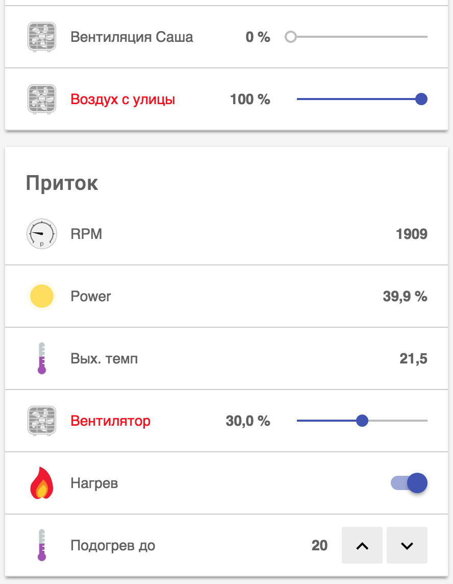
For example, the topic of connecting Modbus devices, their pulling and synchronization of the local state of the device with the Smart Home system, integration with a simple air-supply unit, remained completely behind the scenes. Well, and, perhaps, a comparison with existing systems of similar classes, such as MegaD-328, AMS and even WirenBoard. Perhaps, if there is interest, I will continue.
Also, for now, behind the scenes, with the use of NodeRed, it was possible to integrate the system with Telegram. While working to receive alerts, but you can create a full-fledged bot.
Regarding the project LightHub - with all the cheapness, the controllers were quite a working decision. Honestly, I myself did not believe that a stable working system could be created on the basis of Arduino, but, in my opinion, it was possible.
Of course, much more needs to be done: completely get away from the hardcode (just a little bit left), clean up and refactor the code in some places, carefully document the project, dilute the printed circuit board (now the interface Schilds are soldered simply on the basis of development boards and contain three MAX-485 - (DMX-IN, DMX-OUT, Modbus) and 1-Wire bridge) - and this will become, in fact, a very budget ready-made solution.
Warning: I remind you that the project is still at the level of prototyping boards. Opening the next spoiler, you can damage your aesthetic feelings.
Some pictures 
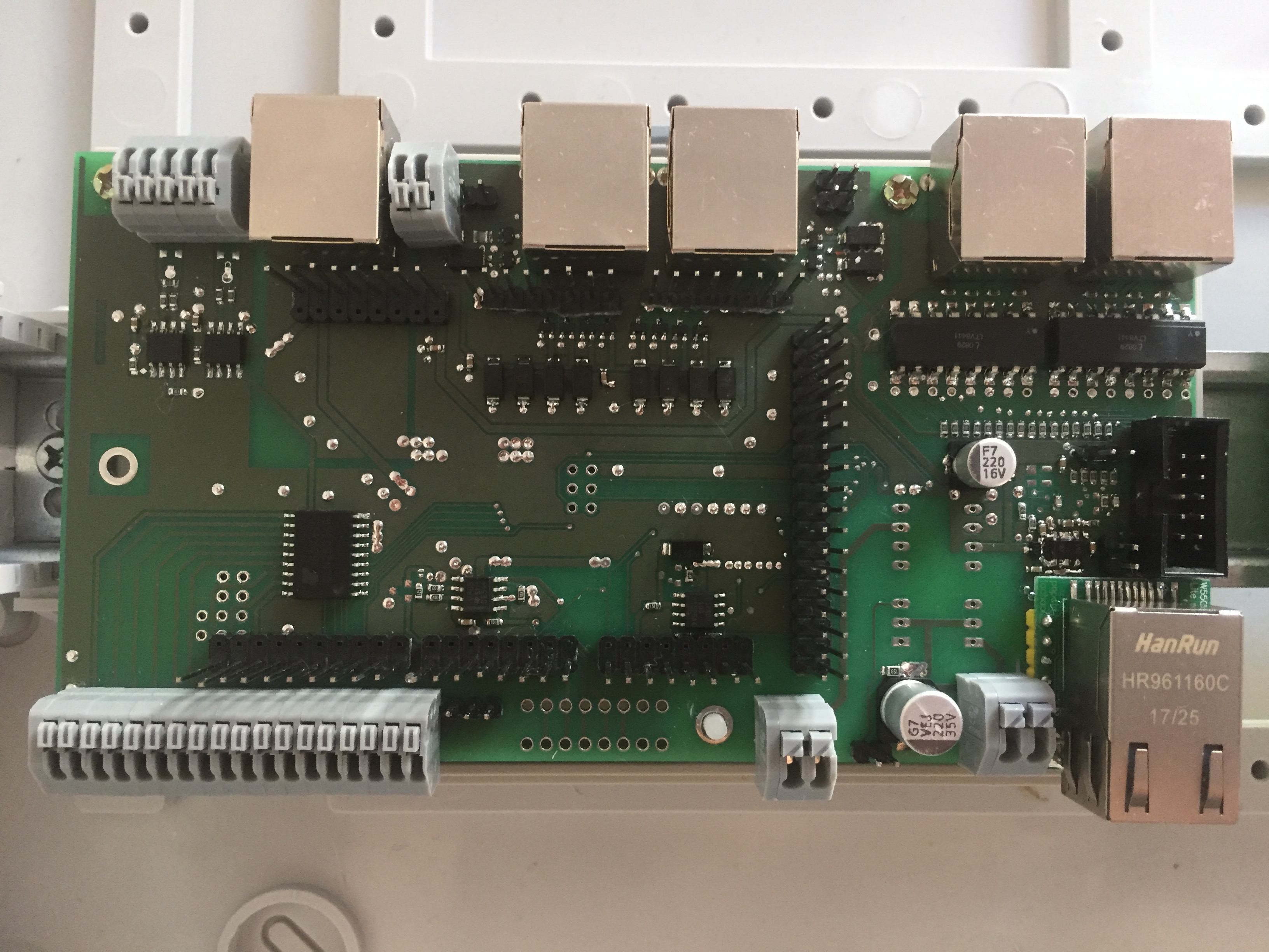
The first controller that controls the LED (60 DMX-512 channels), Modbus (dimmers, inflow), veil flaps;

This is a DMX-512 decoder that is convenient to place where LED strips come to transformers. I - under the false ceiling in the pantry.

And this is the second controller serving 1-wire, switches / sensors and a relay module. (The relay module itself is located right in the terminal box, where it belongs to a place with three phases. I eradicated the neighborhood of 380V and a weak point, wherever possible, after one unsuccessful incident)
The first controller that controls the LED (60 DMX-512 channels), Modbus (dimmers, inflow), veil flaps;
This is a DMX-512 decoder that is convenient to place where LED strips come to transformers. I - under the false ceiling in the pantry.
And this is the second controller serving 1-wire, switches / sensors and a relay module. (The relay module itself is located right in the terminal box, where it belongs to a place with three phases. I eradicated the neighborhood of 380V and a weak point, wherever possible, after one unsuccessful incident)
It is clear that it is necessary to expand the functionality. At least in the direction of wireless sensors / devices. (Although, for example, ZWave can now be used through standard Openhab binding).
The ability to connect, for example, the budget NooLight, probably a good idea. Maybe I’ll think about migration to ESP-8266 for expanding RAM, although I don’t like to go to WiFi from a wired LAN connection from a reliability point of view. Yes, and ESP does not have such a rich periphery as the Arduino Mega. I also plan to record electricity through current sensors and connect the Rotary Encoder to the input.
Also, it would be useful to make the configuration and launch of the controller more User Friendly (visual configurators, etc.). At the same time, I deliberately did not want to turn the controller into a web server with files / pictures, AJAX, etc. In my opinion, this should already be the prerogative of the server. At least on the basis of Raspberry.
But since the project is absolutely Open-source - various options are possible, join.
Also, looking forward to your feedback.
UPDATE:
After the publication of the article, joining forces with one of the residents of Habr and drawing a schematic diagram of LighthHub Shield, began to set the PCB, taking into account all the meaningful experience and comments
- The board will be compatible with both Arduino Mega (5v) and Arduino DUE (ARM 3.3V)
- Built-in Ethernet interface based on Wiznet5500
- 8 opto-isolated digital inputs, 8 digital inputs / outputs with voltage / current protection
- 8 analog inputs with voltage / current protection. In the future, I intend to use analog inputs to control power consumption (current sensors) and to connect external potentiometers (dimmers)
- 8 PWM outputs, 4 of them with powerful output keys (up to 500 mA / 50V) + 4 discrete powerful outputs. They will allow you to connect locally to the controller, for example, several starters or even a not very long RGBW LED strip.
- The UEXT format connector , which will allow, subsequently, to connect compatible peripherals to the controller - for example, additional radio modules for connecting to wireless devices.
- The remaining inputs / outputs will be output without protection to the RJ45 connectors for connecting local devices (relay boards, DAC, etc.)
- Of course, there remain 1-Wire interfaces for connecting temperature sensors, DMX-512 input and output for lighting control, Modbus RTU for everything else
Leave comments on the functionality, as well as the desire to join the order of the first batch of boards, you can here
The next item on the program will be the development of a controller board with an integrated ESP32 module (this will allow you to get away from the Arduino form factor)
All Articles