Homemade text laser projector
In this article I will explain how to make a fairly simple laser projector from the parts at hand.
There are two methods of creating images using a laser - this is a vector and raster scan.
In the case of a vector scan, the laser beam moves in space along the contours of the desired image, disconnecting only for the duration of the transition from one circuit to another.
Due to this, the laser turns out to be switched on most of the time, due to which the formed picture is quite bright.
This method is commonly used in various industrial laser projectors. At the same time, for the rapid movement of a laser beam, it is necessary to use rather complex electronic-mechanical devices - galvanometers. Their prices usually start at $ 80 per pair, and at home they are problematic to make galvanometers ( albeit really ).
The second method of creating an image is raster scanning . In this method, the laser beam consistently moves along all the lines of the image. This method is used in the CRT tubes of old TVs and monitors.
Due to the fact that both types of movements (vertical and horizontal) are performed cyclically, the mechanics can be greatly simplified (compared to vector scanning). In addition, since the formed image consists of separate elements, it is much easier to form it from the program point of view.
The lack of raster scanning - the beam will pass along all elements of the image, even if they do not need to be highlighted, which is why the brightness of the image drops.
It is this method, because of its simplicity, that I wanted to implement in my projector.
To move the laser beam along the line (horizontal scan) is very convenient to use a mirror rotating at a constant speed. Due to the fact that the rotation is continuous, the speed of the beam can be quite large. But the transition from one line to another is more difficult to implement.
The easiest option is to use several lasers aimed at a rotating mirror. The disadvantages of this method are that the number of displayed lines will be determined by the number of lasers used, which complicates the design, and the width of the mirror must be sufficiently large. Although there are advantages - the only moving element in such a system is a mirror, and the use of several lasers makes it possible to achieve a sufficiently high brightness of the image. Here is an example of a projector using this principle .
Another option of scanning that can be found in the network is the combination of vertical and horizontal scanning by using a rotating polyhedral mirror, in which individual face mirrors are located at different angles to the axis of rotation. Thanks to this design of the mirror, when the mirror is rotated from one face to another, the laser beam is deflected to different angles vertically, thereby creating a vertical scan.
Despite the overall simplicity of the resulting projector (only a laser, a mirror with a motor and a synchronization sensor are needed), the method has a big drawback - the great difficulty of making such a multi-faceted mirror at home. Usually, the angle of inclination of the face mirrors has to be adjusted during the assembly process, and this must be done with great precision, which greatly complicates the design of the mirror.
Here is an example of a projector using this principle .
To simplify the design, I decided to use a different sweep principle - a constantly rotating mirror to form a horizontal scan and a periodically oscillating mirror to form a vertical scan.
Where can I get a quickly rotating mirror? From an old laser printer!
In laser printers, a multifaceted (polygonal) mirror mounted on the shaft of a high-speed brushless motor is used to scan a laser beam along a sheet of paper. Usually this engine is mounted on a printed circuit board, which it controls.
I already had a suitable mirror module from the printer:
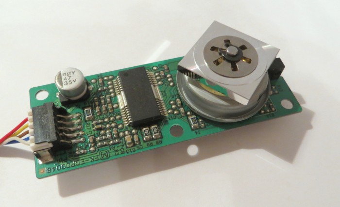
The documentation for the module itself and the chip used in it could not be found, so in order to determine the pinout of the module I had to do a simple reverse engineering. The power lines on the connector are quite simple to find - they are connected to a single electrolytic capacitor on the board. However, just when the power is applied, the engine will not rotate - you need to send a clock signal to the board, which determines the speed of rotation. This signal is a simple meander with a frequency from 20 to 500-1000 Hz (for different models it can be different).
To find the desired line, I took a pulse generator tuned to a frequency of 100 Hz and connected its output through a 470 resistor to all the free lines of the laser module connector. When a signal was sent to the desired line, the motor began to rotate. The speed of rotation of the mirror is very high, subsequent measurements showed that it can exceed 250 rev / sec. But, unfortunately, due to the high speed of rotation, my laser module was quite noisy. For experiments, this is not a problem, but for a permanent projector, this is bad. It is possible that due to the use of a newer mirror module or installation of the structure in the box, the noise level can be significantly reduced.
For the first tests, I used a laser module from a cheap pointer. The module must be fixed so that it can be rotated along several axes - this is necessary in order to correctly direct the laser to the mirror:
Since due to the use of a raster scan, the laser light is distributed over the entire image area, the brightness of the formed image is rather low - the image can only be seen in the dark.
Therefore, after I received the image, I replaced the laser module with another one, which uses a laser diode from a DVD ( an example of making such a module ).
The mounting structure of this laser module is the same as the previous one.
I installed the laser and the polygonal mirror module on a small hardboard plate. The laser must be fixed in the same plane as the mirror. After supplying power from the clock signal to the motor and power to the laser, you need to set the laser so that its beam hits the edges of the mirror. As a result, as the polygonal mirror rotates, a long horizontal laser line is formed.
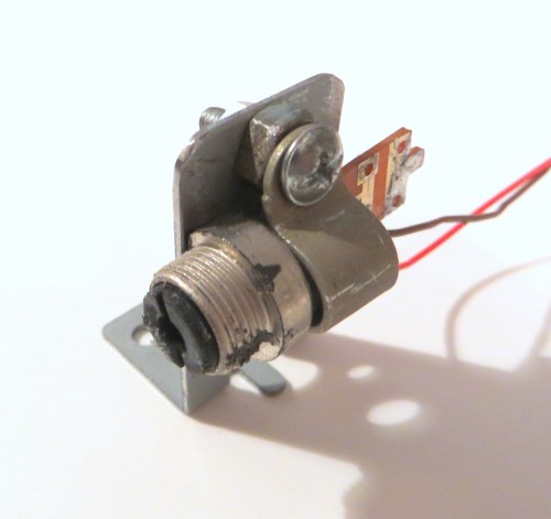
In order for the control microcontroller to track the position of a moving laser beam, a photo sensor is needed. As a photo sensor, I used a photodiode, covered with a piece of cardboard with a slot. The slot is needed in order to more accurately detect the moment the beam hits the photodiode.
This is how the photodiode mount looks (without a slotted cardboard):

During normal operation of the motor, the reflected laser beam must first fall on the photo sensor, and then on the vertical scanning mirror.
After the sensor was installed, I checked its operation by applying a voltage across it through a resistor. I watched the signal from the sensor with an oscilloscope - its amplitude was enough to connect the sensor directly to the microcontroller's GPIO input.
As I mentioned earlier, I used a periodically oscillating mirror to form a vertical scan. How can I make a drive of such a mirror?
The easiest option is to use a loaded electromagnet. Sometimes in the simplest designs of laser projectors use mirrors attached to ordinary speakers. But this solution has a large number of flaws (poor repeatability of results, low manufacturability of the design, difficulty in calibration).
In my design of the projector, I decided to use the BLDC motor from the DVD to control the vertical scan mirror. Since the projector was originally planned for text output, this meant that the displayed lines would be slightly, which means that the mirror should be turned at a small angle.
The BLDC motor from the DVD contains three windings that make up the stator . If one of the windings is connected to a positive voltage source, and the other two are alternately connected to its negative, then the motor rotor will oscillate. The maximum angular range of oscillations is determined by the design of the motor, in particular, by the number of its poles. For a DVD motor, this span does not exceed 30 degrees. Due to the sufficiently high power of such a motor, ease of control (you need only two keys), the rotational motion, this motor is very well suited for making a simple text-based laser projector.
This is what my motor looks like with a mirror glued to it:

It is worth paying attention to the fact that the reflecting surface of the mirror should be ahead, that is, not covered with glass.
Here is the whole projector:
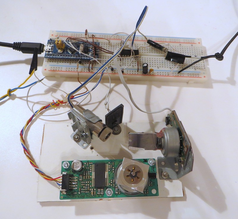
Close-up projection part:
The polygonal mirror rotates clockwise so that the laser beam moves from left to right.
There is already installed a powerful laser diode from the DVD (inside the collimator). The vertical mirror is installed in such a way that the projected image is directed upwards - in my case, to the ceiling of the room.
As you can see from the photo, the stm32f103 microcontroller mounted on a small debugging board (Blue Pill) controls the laser and the mechanics of the projector. This board is inserted in the Breadboard.
Design scheme:
As I mentioned earlier, to control the motor of a polygonal mirror, only one signal is needed - clocking (“POLY_CLOCK”), which is produced by one of the stm32 timers operating in the PWM mode. The frequency and duty cycle of this signal remains unchanged during the operation of the projector. I use a separate 12 V power supply to power the motor board.
Two PWM signals for controlling the position of the vertical scanning mirror form another microcontroller timer. These signals are connected to the ULN2003A microcircuit, which controls the DVD motor. Thus, by setting different duty cycle PWM channels of this timer, you can change the angle of rotation of the motor.
Unfortunately, in its current form, the design has no feedback on the position of the mirror. This means that the microcontroller can set the mirrors in motion, but he will not “know” his current position. Due to the inertia of the rotor of the motor and the inductance of the coils, the change in the direction of movement of the mirror also occurs with some delay.
All this leads to two consequences:
However, due to the lack of feedback, the design is very simple.
The process of image formation by the projector is also quite simple:
My laser modulation is also implemented using one of the keys of the ULN2003A microcircuit. Resistor R3 is needed for the simplest protection of the laser diode from too much current. It is mounted directly on the end of the laser wire and insulated. To power the laser, I used a separate adjustable power supply . It is important to control the current consumed by the laser and ensure that it does not exceed the maximum allowable value for the laser diode used.
An example of a molded image (font with a height of 8 lines):
Some distortion of the proportions of the text due to the fact that the projector shines on the wall at an angle.
Now each cycle of oscillations of the vertical scanning mirror consists of 32 steps (one step corresponds to the rotation of the polygonal mirror by 1 face).
In the current implementation, the projector can output about 14 full lines, the remaining lines either merge with each other, or mix incorrectly with the rest.
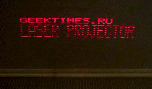
The photo at the beginning of the article also uses a font with a height of 8 lines. As you can see, even two lines of text are more or less normally displayed.
At the same time, the character generator table in this project contains fonts 12 and 6 lines high:

This photo clearly shows the varying density of lines.
An example of a "running line" displayed by such a projector:
In the video image flickers vertically, in reality, this effect is invisible to the eye.
→ Project files
Introduction
There are two methods of creating images using a laser - this is a vector and raster scan.
In the case of a vector scan, the laser beam moves in space along the contours of the desired image, disconnecting only for the duration of the transition from one circuit to another.
Due to this, the laser turns out to be switched on most of the time, due to which the formed picture is quite bright.
This method is commonly used in various industrial laser projectors. At the same time, for the rapid movement of a laser beam, it is necessary to use rather complex electronic-mechanical devices - galvanometers. Their prices usually start at $ 80 per pair, and at home they are problematic to make galvanometers ( albeit really ).
The second method of creating an image is raster scanning . In this method, the laser beam consistently moves along all the lines of the image. This method is used in the CRT tubes of old TVs and monitors.
Due to the fact that both types of movements (vertical and horizontal) are performed cyclically, the mechanics can be greatly simplified (compared to vector scanning). In addition, since the formed image consists of separate elements, it is much easier to form it from the program point of view.
The lack of raster scanning - the beam will pass along all elements of the image, even if they do not need to be highlighted, which is why the brightness of the image drops.
It is this method, because of its simplicity, that I wanted to implement in my projector.
To move the laser beam along the line (horizontal scan) is very convenient to use a mirror rotating at a constant speed. Due to the fact that the rotation is continuous, the speed of the beam can be quite large. But the transition from one line to another is more difficult to implement.
The easiest option is to use several lasers aimed at a rotating mirror. The disadvantages of this method are that the number of displayed lines will be determined by the number of lasers used, which complicates the design, and the width of the mirror must be sufficiently large. Although there are advantages - the only moving element in such a system is a mirror, and the use of several lasers makes it possible to achieve a sufficiently high brightness of the image. Here is an example of a projector using this principle .
Another option of scanning that can be found in the network is the combination of vertical and horizontal scanning by using a rotating polyhedral mirror, in which individual face mirrors are located at different angles to the axis of rotation. Thanks to this design of the mirror, when the mirror is rotated from one face to another, the laser beam is deflected to different angles vertically, thereby creating a vertical scan.
Despite the overall simplicity of the resulting projector (only a laser, a mirror with a motor and a synchronization sensor are needed), the method has a big drawback - the great difficulty of making such a multi-faceted mirror at home. Usually, the angle of inclination of the face mirrors has to be adjusted during the assembly process, and this must be done with great precision, which greatly complicates the design of the mirror.
Here is an example of a projector using this principle .
To simplify the design, I decided to use a different sweep principle - a constantly rotating mirror to form a horizontal scan and a periodically oscillating mirror to form a vertical scan.
Implementation
Horizontal scan
Where can I get a quickly rotating mirror? From an old laser printer!
In laser printers, a multifaceted (polygonal) mirror mounted on the shaft of a high-speed brushless motor is used to scan a laser beam along a sheet of paper. Usually this engine is mounted on a printed circuit board, which it controls.
I already had a suitable mirror module from the printer:
The documentation for the module itself and the chip used in it could not be found, so in order to determine the pinout of the module I had to do a simple reverse engineering. The power lines on the connector are quite simple to find - they are connected to a single electrolytic capacitor on the board. However, just when the power is applied, the engine will not rotate - you need to send a clock signal to the board, which determines the speed of rotation. This signal is a simple meander with a frequency from 20 to 500-1000 Hz (for different models it can be different).
To find the desired line, I took a pulse generator tuned to a frequency of 100 Hz and connected its output through a 470 resistor to all the free lines of the laser module connector. When a signal was sent to the desired line, the motor began to rotate. The speed of rotation of the mirror is very high, subsequent measurements showed that it can exceed 250 rev / sec. But, unfortunately, due to the high speed of rotation, my laser module was quite noisy. For experiments, this is not a problem, but for a permanent projector, this is bad. It is possible that due to the use of a newer mirror module or installation of the structure in the box, the noise level can be significantly reduced.
Laser
For the first tests, I used a laser module from a cheap pointer. The module must be fixed so that it can be rotated along several axes - this is necessary in order to correctly direct the laser to the mirror:
Since due to the use of a raster scan, the laser light is distributed over the entire image area, the brightness of the formed image is rather low - the image can only be seen in the dark.
Therefore, after I received the image, I replaced the laser module with another one, which uses a laser diode from a DVD ( an example of making such a module ).
Attention - the DVD laser is very dangerous for the eyes, all work with such a laser should be carried out in special protective glasses!
The mounting structure of this laser module is the same as the previous one.
I installed the laser and the polygonal mirror module on a small hardboard plate. The laser must be fixed in the same plane as the mirror. After supplying power from the clock signal to the motor and power to the laser, you need to set the laser so that its beam hits the edges of the mirror. As a result, as the polygonal mirror rotates, a long horizontal laser line is formed.
Sync Photo Sensor
In order for the control microcontroller to track the position of a moving laser beam, a photo sensor is needed. As a photo sensor, I used a photodiode, covered with a piece of cardboard with a slot. The slot is needed in order to more accurately detect the moment the beam hits the photodiode.
This is how the photodiode mount looks (without a slotted cardboard):
During normal operation of the motor, the reflected laser beam must first fall on the photo sensor, and then on the vertical scanning mirror.
After the sensor was installed, I checked its operation by applying a voltage across it through a resistor. I watched the signal from the sensor with an oscilloscope - its amplitude was enough to connect the sensor directly to the microcontroller's GPIO input.
Vertical scan
As I mentioned earlier, I used a periodically oscillating mirror to form a vertical scan. How can I make a drive of such a mirror?
The easiest option is to use a loaded electromagnet. Sometimes in the simplest designs of laser projectors use mirrors attached to ordinary speakers. But this solution has a large number of flaws (poor repeatability of results, low manufacturability of the design, difficulty in calibration).
In my design of the projector, I decided to use the BLDC motor from the DVD to control the vertical scan mirror. Since the projector was originally planned for text output, this meant that the displayed lines would be slightly, which means that the mirror should be turned at a small angle.
The BLDC motor from the DVD contains three windings that make up the stator . If one of the windings is connected to a positive voltage source, and the other two are alternately connected to its negative, then the motor rotor will oscillate. The maximum angular range of oscillations is determined by the design of the motor, in particular, by the number of its poles. For a DVD motor, this span does not exceed 30 degrees. Due to the sufficiently high power of such a motor, ease of control (you need only two keys), the rotational motion, this motor is very well suited for making a simple text-based laser projector.
This is what my motor looks like with a mirror glued to it:
It is worth paying attention to the fact that the reflecting surface of the mirror should be ahead, that is, not covered with glass.
Design as a whole
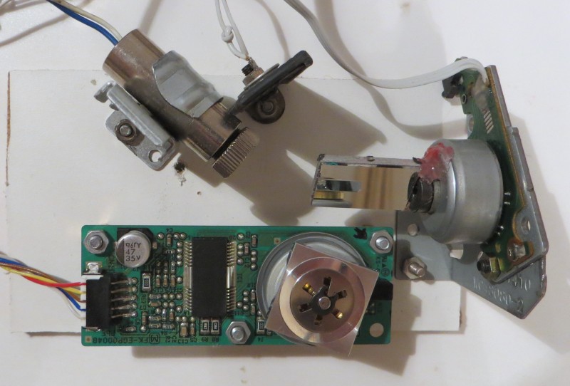
Here is the whole projector:
Close-up projection part:
The polygonal mirror rotates clockwise so that the laser beam moves from left to right.
There is already installed a powerful laser diode from the DVD (inside the collimator). The vertical mirror is installed in such a way that the projected image is directed upwards - in my case, to the ceiling of the room.
As you can see from the photo, the stm32f103 microcontroller mounted on a small debugging board (Blue Pill) controls the laser and the mechanics of the projector. This board is inserted in the Breadboard.
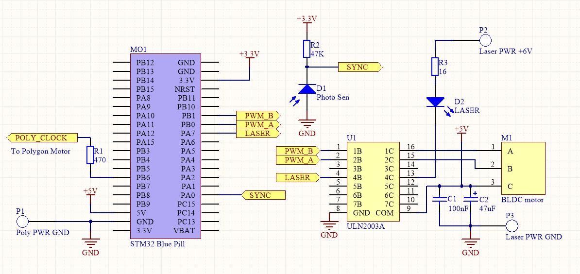
Design scheme:
As I mentioned earlier, to control the motor of a polygonal mirror, only one signal is needed - clocking (“POLY_CLOCK”), which is produced by one of the stm32 timers operating in the PWM mode. The frequency and duty cycle of this signal remains unchanged during the operation of the projector. I use a separate 12 V power supply to power the motor board.
Two PWM signals for controlling the position of the vertical scanning mirror form another microcontroller timer. These signals are connected to the ULN2003A microcircuit, which controls the DVD motor. Thus, by setting different duty cycle PWM channels of this timer, you can change the angle of rotation of the motor.
Unfortunately, in its current form, the design has no feedback on the position of the mirror. This means that the microcontroller can set the mirrors in motion, but he will not “know” his current position. Due to the inertia of the rotor of the motor and the inductance of the coils, the change in the direction of movement of the mirror also occurs with some delay.
All this leads to two consequences:
- Line density is variable. This is due to the fact that the speed of rotation of the mirror is not controlled.
- A large part of the lines can not be used. The vertical mirror oscillates cyclically, so that part of the time line could be displayed from top to bottom, and the other part - from bottom to top. As a result, due to the lack of position data, it is necessary to display lines only when the motor moves in one direction. Since only part of the lines are displayed, the brightness of the image decreases (that is, the laser is not fully used).
However, due to the lack of feedback, the design is very simple.
The process of image formation by the projector is also quite simple:
- Each time a laser beam hits a photodiode, an interrupt is generated in the microcontroller.
In this interrupt, the controller determines the current horizontal speed. After that, a special synchronization timer is reset. This is the moment of synchronization. - This synchronization timer at certain points in time forms its interrupts corresponding to the necessary points in time in the process of horizontal scanning.
- In particular, some time after the synchronization moment it is necessary to start forming the laser control signal. In my design I am shaping it with a bunch of DMA + SPI. In fact, with the help of these modules at the right time, one of the lines of the image is output a bit to the output of the MOSI SPI.
- After the output of the image in the line is over, you must forcibly turn on the laser. This is necessary so that the photodiode can again take its light.
My laser modulation is also implemented using one of the keys of the ULN2003A microcircuit. Resistor R3 is needed for the simplest protection of the laser diode from too much current. It is mounted directly on the end of the laser wire and insulated. To power the laser, I used a separate adjustable power supply . It is important to control the current consumed by the laser and ensure that it does not exceed the maximum allowable value for the laser diode used.
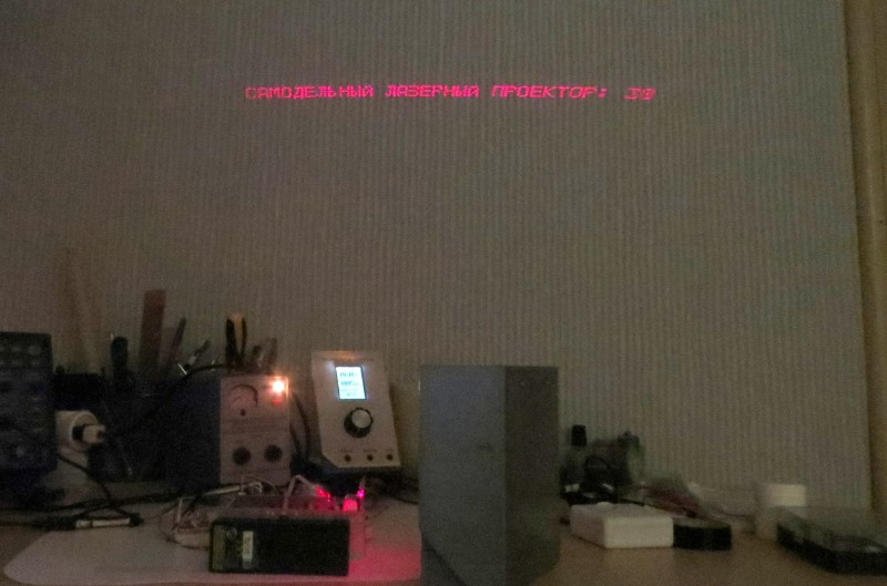
An example of a molded image (font with a height of 8 lines):
Some distortion of the proportions of the text due to the fact that the projector shines on the wall at an angle.
Now each cycle of oscillations of the vertical scanning mirror consists of 32 steps (one step corresponds to the rotation of the polygonal mirror by 1 face).
In the current implementation, the projector can output about 14 full lines, the remaining lines either merge with each other, or mix incorrectly with the rest.
The photo at the beginning of the article also uses a font with a height of 8 lines. As you can see, even two lines of text are more or less normally displayed.
At the same time, the character generator table in this project contains fonts 12 and 6 lines high:
This photo clearly shows the varying density of lines.
An example of a "running line" displayed by such a projector:
In the video image flickers vertically, in reality, this effect is invisible to the eye.
→ Project files
All Articles