Vacuum gauge for pressure transmitter PMT-2
Vacuum gauge for pressure transmitter PMT-2
Hi GeekTimes! Not long ago, I began assembling an ion-plasma (magnetron) deposition setup ( Part 1 ). In the process of testing and working with the installation, many decisions were made on its modernization and improvement.
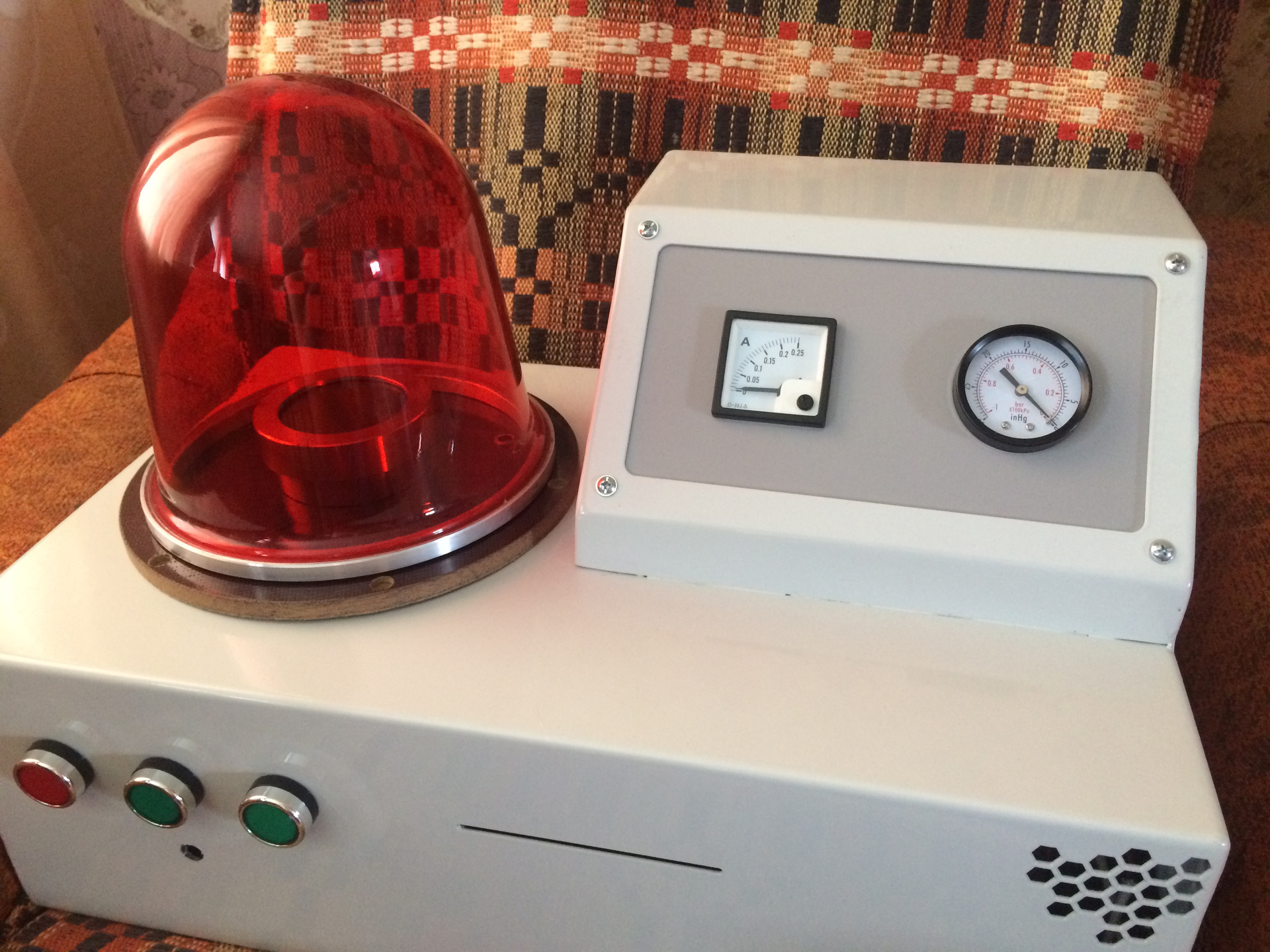
One such improvement was the introduction of a vacuum gauge in the installation to measure the depth of vacuum. Seeing that one of my personal requirements is the mobility of the installation and the location of all its components inside the device, I had to abandon external vacuum gauges, for example, such as VIT-2. In addition, I need to observe the moment of the budget for the installation, and the purchased vacuum gauges are not cheap enough. I chose the PMT-2 lamp as a detecting device, as I had little experience with it and its cost is quite acceptable.

So, how does this gauge transducer work? The principle of operation of thermal (thermocouple) converters to which the PMT-2 lamp belongs is based on the dependence of the molecular thermal conductivity of a gas on its pressure. Heat transfer occurs from a thin metal filament heated by an electric current through a rarefied gas to a vacuum pump at room temperature.
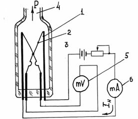
In a PMT-2 thermocouple converter, holders (1) are fixed in a glass flask, on which a V-shaped heater made of thin wire (2) is fixed by spot welding, to the midpoint of which a platinum-rhodium-plated thermocouple is welded (3).
A constant current IH is passed through the heater filament (2), which heats the junction of the thermocouple (3), and a thermoelectric voltage appears in its circuit. Since the temperature of the heater depends on the pressure (density) of the gas, its change will lead to a change in the EFV. thermocouples, which is measured by a millivoltmeter (5), and the filament current IH is regulated by a rheostat and measured by the instrument (6).
The PMT-2 lamp is a rather coarse pressure gauge sharpened under the VIT. Calibrated in sealed state. The filament current is selected on a scale HIT, 100 divisions - the filament current.
After the lamp is otpaivaetsya (cut off, it is like an ampoule), soldered into the vacuum system.
Let us now turn to the description of the construction of my vacuum gauge: Before receiving the readings from the lamp, it is necessary to power its filament and apply about 100 mA (112-116 mA) to it. For this, a voltage regulator purchased on eBay was taken and, together with a series-connected resistor, was connected to the lamp. Since the regulator with its lowest voltage value gave a very large current value, I had to use a resistor.
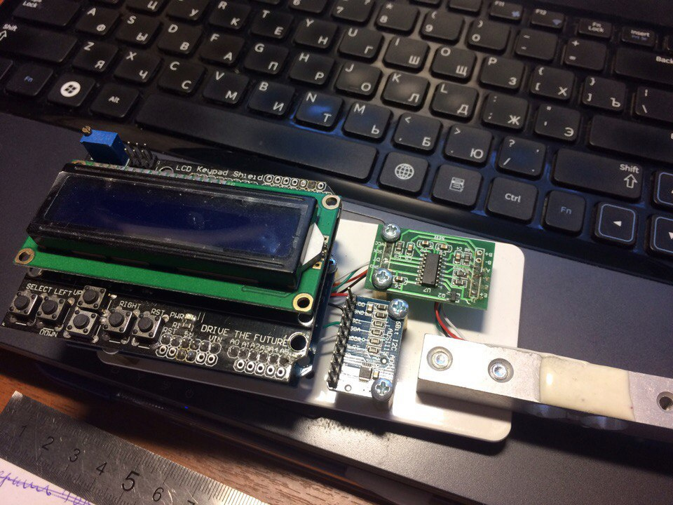
Measuring vacuum implies measuring voltage in the millivolt range, for this, not on the same trade portal, not sophisticated electronics were purchased: the Arduino Uno microcontroller board, the LCD1602 module and the ADS1115 ADC at 16Bit.
In the ADC module there are 4 analog channels, I used only one, connecting the inputs of the Arduino SDA and SCL to the corresponding outputs of the ADC module. A lamp thermocouple connected to the terminals GND and A0 module.
This is the end of the connection and you can go to the description of the firmware (sketch):
The firmware text is not complicated and not large, since library functions are mainly used. The main difficulty arose only when translating the voltage values into pressure values, since this dependence is not linear.

This calibration dependence was digitized and projected, thereby obtaining the formula by which the calculation of reduced pressure is performed quite accurately.
Device video:
As for the further implementation of my project, I want to throw out the pump from the inside of the installation, it still doesn’t have enough performance and takes up a lot of space, instead the magnetron cooling system will rise (radiator with cooler and pump, it is possible that there is still a small sealed volume with coolant). Hoses I want to replace the normal reinforced vacuum (they are not very expensive). Of course, it is necessary to build in a vacuum measurement system with a lamp (at least the same PMT-2). And probably the most difficult thing: the implementation of a normal base (it’s now textolite) and the magnetron, I want to realize all this from aluminum, since the mating plane of the base with the cap must be ground (with a textolite this does not work), and the magnetron still needs to be redone - I want to bother with stainless steel and make almost all the details of duralumin on the CNC portal machine, which I also collect. I also want to throw out a white disk from the LATRA and, instead of it, put a drive, for example, and control the potentiometer from the dashboard. And quite in the distant future in general, get rid of Latr.
Hi GeekTimes! Not long ago, I began assembling an ion-plasma (magnetron) deposition setup ( Part 1 ). In the process of testing and working with the installation, many decisions were made on its modernization and improvement.
One such improvement was the introduction of a vacuum gauge in the installation to measure the depth of vacuum. Seeing that one of my personal requirements is the mobility of the installation and the location of all its components inside the device, I had to abandon external vacuum gauges, for example, such as VIT-2. In addition, I need to observe the moment of the budget for the installation, and the purchased vacuum gauges are not cheap enough. I chose the PMT-2 lamp as a detecting device, as I had little experience with it and its cost is quite acceptable.
So, how does this gauge transducer work? The principle of operation of thermal (thermocouple) converters to which the PMT-2 lamp belongs is based on the dependence of the molecular thermal conductivity of a gas on its pressure. Heat transfer occurs from a thin metal filament heated by an electric current through a rarefied gas to a vacuum pump at room temperature.
In a PMT-2 thermocouple converter, holders (1) are fixed in a glass flask, on which a V-shaped heater made of thin wire (2) is fixed by spot welding, to the midpoint of which a platinum-rhodium-plated thermocouple is welded (3).
A constant current IH is passed through the heater filament (2), which heats the junction of the thermocouple (3), and a thermoelectric voltage appears in its circuit. Since the temperature of the heater depends on the pressure (density) of the gas, its change will lead to a change in the EFV. thermocouples, which is measured by a millivoltmeter (5), and the filament current IH is regulated by a rheostat and measured by the instrument (6).
The PMT-2 lamp is a rather coarse pressure gauge sharpened under the VIT. Calibrated in sealed state. The filament current is selected on a scale HIT, 100 divisions - the filament current.
After the lamp is otpaivaetsya (cut off, it is like an ampoule), soldered into the vacuum system.
Let us now turn to the description of the construction of my vacuum gauge: Before receiving the readings from the lamp, it is necessary to power its filament and apply about 100 mA (112-116 mA) to it. For this, a voltage regulator purchased on eBay was taken and, together with a series-connected resistor, was connected to the lamp. Since the regulator with its lowest voltage value gave a very large current value, I had to use a resistor.
Measuring vacuum implies measuring voltage in the millivolt range, for this, not on the same trade portal, not sophisticated electronics were purchased: the Arduino Uno microcontroller board, the LCD1602 module and the ADS1115 ADC at 16Bit.
In the ADC module there are 4 analog channels, I used only one, connecting the inputs of the Arduino SDA and SCL to the corresponding outputs of the ADC module. A lamp thermocouple connected to the terminals GND and A0 module.
This is the end of the connection and you can go to the description of the firmware (sketch):
#include <LiquidCrystal.h> #include <EEPROM.h> #include <Wire.h> #include <Adafruit_ADS1015.h> Adafruit_ADS1115 ads; LiquidCrystal lcd(8, 9, 4, 5, 6, 7); long val = 0; long zero = 0; int V = 0; int F = 0; int Time = 100; void setup() { lcd.begin(16, 2); Serial.begin(9600); lcd.setCursor(0,0); lcd.print("CybSys presents"); // // ads.setGain(GAIN_TWOTHIRDS); // 2/3x gain +/- 6.144V 1 bit = 3mV 0.1875mV (default) // ads.setGain(GAIN_ONE); // 1x gain +/- 4.096V 1 bit = 2mV 0.125mV // ads.setGain(GAIN_TWO); // 2x gain +/- 2.048V 1 bit = 1mV 0.0625mV // ads.setGain(GAIN_FOUR); // 4x gain +/- 1.024V 1 bit = 0.5mV 0.03125mV // ads.setGain(GAIN_EIGHT); // 8x gain +/- 0.512V 1 bit = 0.25mV 0.015625mV ads.setGain(GAIN_SIXTEEN); // 16x gain +/- 0.256V 1 bit = 0.125mV 0.0078125mV ads.begin(); } void loop() { int16_t adc0; lcd.setCursor(0,0); lcd.print("Press: "); lcd.setCursor(0,1); lcd.print("Vol:"); adc0 = ads.readADC_SingleEnded(0); float voltage = (adc0 * (0.256/32767.5))*1000; float pres = 2.217*exp(-voltage/0.3134)+0.175*exp(-voltage/1.97)+543.59*exp(- voltage/211689.45)+(-543.57); lcd.setCursor(7,0); lcd.print(pres,5); lcd.setCursor(5,1); lcd.print (voltage,5); Serial.print("Vol:"); Serial.println(voltage, 5); delay(200); }
The firmware text is not complicated and not large, since library functions are mainly used. The main difficulty arose only when translating the voltage values into pressure values, since this dependence is not linear.
This calibration dependence was digitized and projected, thereby obtaining the formula by which the calculation of reduced pressure is performed quite accurately.
Device video:
As for the further implementation of my project, I want to throw out the pump from the inside of the installation, it still doesn’t have enough performance and takes up a lot of space, instead the magnetron cooling system will rise (radiator with cooler and pump, it is possible that there is still a small sealed volume with coolant). Hoses I want to replace the normal reinforced vacuum (they are not very expensive). Of course, it is necessary to build in a vacuum measurement system with a lamp (at least the same PMT-2). And probably the most difficult thing: the implementation of a normal base (it’s now textolite) and the magnetron, I want to realize all this from aluminum, since the mating plane of the base with the cap must be ground (with a textolite this does not work), and the magnetron still needs to be redone - I want to bother with stainless steel and make almost all the details of duralumin on the CNC portal machine, which I also collect. I also want to throw out a white disk from the LATRA and, instead of it, put a drive, for example, and control the potentiometer from the dashboard. And quite in the distant future in general, get rid of Latr.
All Articles