Programming and data exchange with "ARDUINO" via WI-FI via ESP8266 Part One
Like many other DIY products, I regularly use AVR microcontrollers for all sorts of amateur crafts. And thanks to the concept of "Arduino", these crafts are now becoming more elegant. Indeed, for some 300-400 rubles, we get a miniature multilayer board with a mask, silk-screen printing and with a microcontroller's periphery completely divorced on it (in SMD version!). I'm not talking about all sorts of plug-ins of the same "Arduino" series: sensors, controllers, displays, and entire sets, so we need additional peripherals. And again, everything is also inexpensive and in excellent performance. Practically, there is no need to dilute something and finish it on the “knee”.
But all these various amateur handicrafts require, naturally, preliminary programming. And in the future with various improvements, I constantly have to reflash these crafts. It is clear that it is more convenient to do it remotely than to constantly carry them to the usual programmer. In general, thanks to the same Arduino platform, there are a lot of options here: Bluetooth, ZigBee, a radio channel with your personal protocol, IR, and even Wi-Fi. All of them allow you to establish a wireless contact with your microcontroller. But we will focus on the latest version. There are four main reasons:
1: modern, internet of things!
2: there is a wireless router in each apartment, register your devices in the home network and voila!
3: Your crafts make a revolutionary leap in their development; Not only can they be programmed at a distance, they can now also communicate with the world around them: the electronic clock independently takes the exact time from the NTP servers, the actuators are controlled from the other end of the city or country, the recording devices store the accumulated data in cloud etc. etc.
4: There is a wonderful series of ESP8266 chips on whichit is not very easy to implement all this.
Further, in this article, using the example of a mechanical hand on servo drives, remote programming and data exchange with a PC (or whatever) with AVR microcontroller devices will be disassembled and demonstrated. Immediately I want to note that all the programs listed below are purely demonstration and do not have any commercial value. Therefore, claims, such as why the programmer is so castrated and little functional, or why there are no additional services that are everywhere, are not accepted. Since the codes are open, anyone can finish them on their own, for work, as long as there are enough of them.
It is assumed that the reader is already familiar with the “Arduino” modules (shields) and with the connection and firmware of ESP8266. In fact, a huge amount of materials explaining the basics of working with these devices has been posted on the Web and I would not like to repeat here. For beginners at the end of the article there is a list of useful links on these issues, where you can find a lot of information, why all this does not work for you . In my experience as a former electronics engineer, I can responsibly state that 99% of the problems are as follows:
1. Bad contacts. Since the “Arduino” shields imply switching with each other through the wires like “papa-mama”, and not through soldering, then very often something, somewhere, yes moves away. Check. And in general, as they say, electronics is the science of contacts.
2. Problems with nutrition. Do not supply 5 volts of power to where required 3.3. Sometimes from ESP8266 from this comes smoke. Although on the other hand the logical signals from the five-volt devices, it digests without problems.
3. Problems with sufficient power supply. ESP8266 has a vile nature and can sometimes consume almost three hundred milliampere, although it could have been satisfied with thirty before. Correspondingly, the sickly 3.3 volt stabilizer of the Arduino board, to which you are no doubt confused, was hooked up and immediately dropped to microscopic values. And you can not understand why it works, then no.
4. Confusion with the findings. Always check which signals go where. The RXD receiver must connect to the TXD transmitter, as well as the TXD to RXD, but the MOSI must connect to the MOSI, and the MISO to the MISO, and so on.
5. Do not count on in-circuit pull-up resistors in ESP8266, always pull the leads to zero or power, after 5-10 kilohm external resistors, and not just a jumper. Otherwise, you can at best get unprecedented current consumption, and then smell the unpleasant smell of burning plastic.
6. Shoals of software. Since the software for individual users is written by the same enthusiasts, then periodically glitches of the firmware itself and bugs when updating versions of the same firmware. It is treated by crawling on the appropriate forums, sometimes even in English. Some comrades even claimed that the ESP microcircuit itself is damp as the weather in St. Petersburg, but on the other hand there is also the opinion that since 2014 (the year of its first release) the situation has drastically improved (unlike the weather).
7. Mysterious glitches. This is a rare but nerve-consuming phenomenon. For example, for me, one “Arduino” device did not remotely sew. Rather, it was but with errors. But it was done without errors, if a loop from the programmer was hanging on it (but without the programmer itself). “AHA,” I said to myself and soldered a 15 pF capacitor between the data output and the sync output. It all worked. But the day is killed.
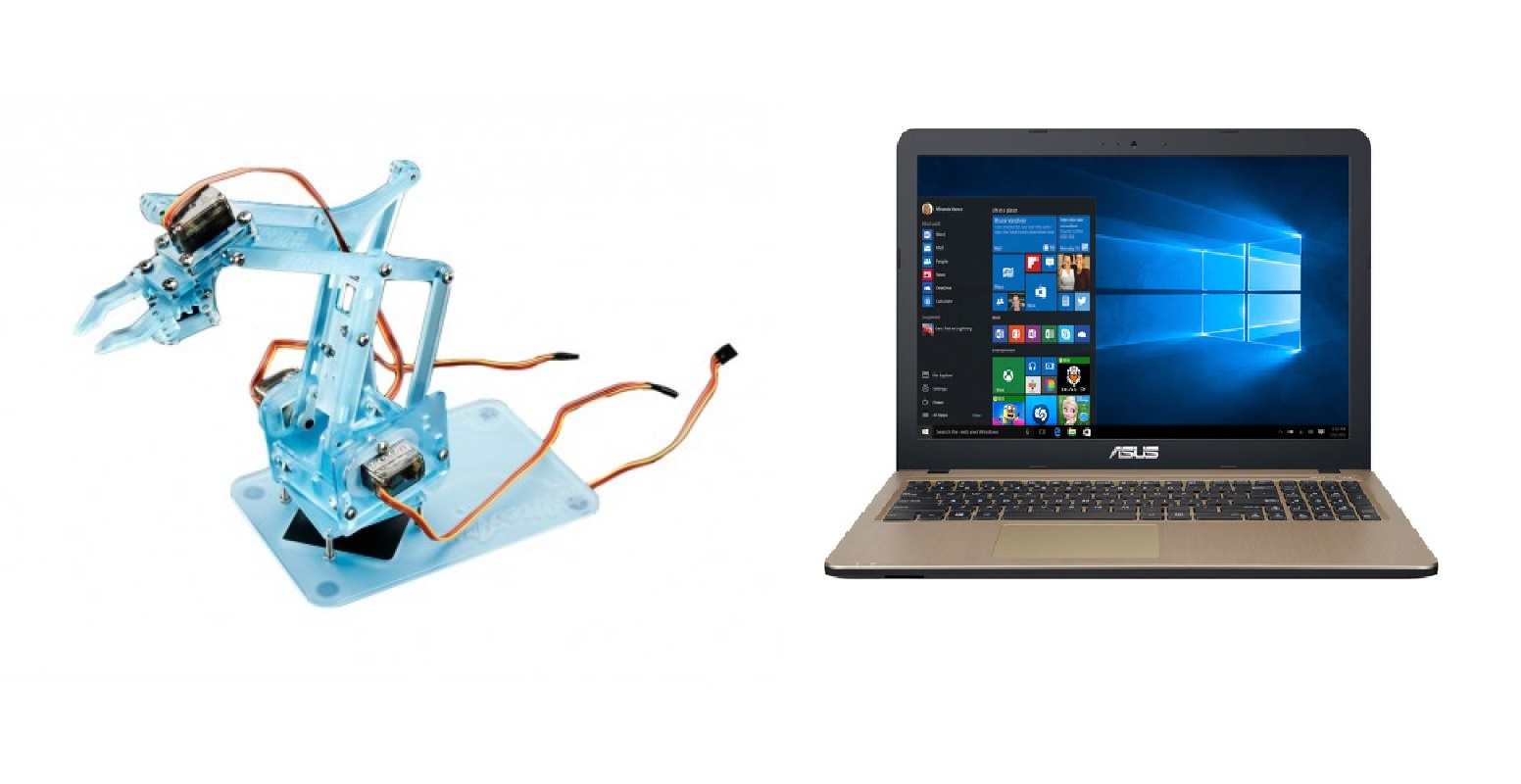
So let's start with the simplest. We have a mechanical limb MechArm (but not such as Howard Volovits collected) made in China and a personal computer with Windows. The task is remote firmware installation and management from a computer.
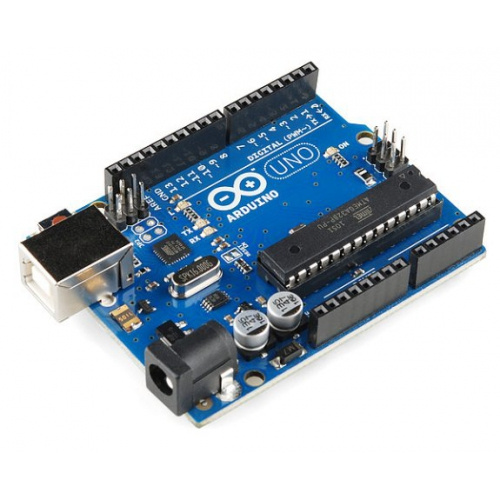
For the controlling controller, take the cute Arduino Nano miniature scarf with the ATmega328P stone. This board is perfectly crammed into a mechanical arm.

Now we will define how we will program it. There are three main ways most suitable for remote firmware: through the SPI interface, through the built-in loader, through the JTAG port.
The easiest option is of course the built-in bootloader (bootloader). This is a pre-written FLASH memory, a program that receives a code according to a certain protocol (say, by the simplest UART) and writes it to the location of the loaded program using special commands. This is how the ARDUINO IDE bootloader, for example, works. After a reset or start, the loader waits for a while for the data to be received and if it does not wait, it starts the execution of the program from the zero address. If the data arrives, he writes them to the program section. After the next reset, the loaded program starts to run. In detail, perhaps, I described inaccurately, but the essence is this. As a result, we need only three outputs for programming: an RTD receiver, a RESET reset, and GND ground. In general, the TRD transmitter is also used to verify the recorded program, but for simple demonstration applications (not for a nuclear power plant), the test can be omitted.
The loader itself is written in assembly language, there are examples of simple loaders in datasheets on AVR. You can dig out the existing loader, if it is in the public domain and just use it in the finished form, if you know the protocol for which it works. The only caveat is that this requires setting the AVR into a special mode, by flashing special fusion bits, which is done by a regular programmer, and then they can also sew the bootloader into the microcontroller’s memory (that is, it will not do without the programmer once).
The second option is SPI serial programming. There is no internal loader here, but we program by sending special commands and then data via the above interface. Here we have an external loader, but you still need to write it. When transferring, in addition to RESET and GND, there are already four additional outputs MOSI, MISO - data, SLK synchronization, CS - chip selection. But in general, you can also remove MISO and CS. The data will only be accepted (there will be no verification of the program), and we have only one crystal anyway.
Each approach has its pros and cons (and I did not consider JTAG at all, since human life is short). But in the end I was inclined to SPI because I was too lazy to write on an assembler, but I did not find any open boot loaders (I just didn’t search well).
To build a wireless channel, I, as already mentioned, chose the extremely well-known ESP8266 microcircuit, the microcontroller, or rather the whole SoC (System-on-Chip) of the Chinese manufacturer Espressif with Wi-Fi interface. In addition to Wi-Fi, it is distinguished by the ability to execute programs from an external flash memory. Specifically, for my project, I took ESP8266-07 with 512 KB of memory on board.

In general, any ESP8266 is suitable where there are extra legs for implementing SPI. Therefore, the simplest ESP8266-01 does not suit us, since it has very few legs for I / O ports. But on the other hand, the difference in price for them is less than one hundred rubles, and they are equally available. Well, large debugging boards with ESP, where, for convenience, a bunch of peripherals are divorced, we also don’t fit, because they don’t get in, where we want to shove them, into our mechanical arm.
The global essence of the idea in general was as follows. From the computer to the ESP without wires via WI-FI (within your home network) the body of the program loaded into the microcontroller is transmitted. And ESP already by wire using the SPI interface writes this program directly to the flash memory of the microcontroller. Then it naturally drops it and allows the loaded program to run. In addition, there should be an independent unit in ESP, which also manages the data exchange with the microcontroller, since we want not only to program, but also to exchange data with it. In particular, for the project with MechArm, after recording the program, we still transmit the servo control signals in order to put this hand in motion. Therefore, on ESP itself, it is desirable for us to raise a TCP server for transmitting a program and a UDP server for managing MechArm. Accordingly, these servers join the home network and carefully listen to whether there are any people willing to upload new code to MechaArm or wave to someone.
So, I found on the web, firmware already allowing to program AVR over the air, but the main problem is that for what other this firmware cannot be used anymore. And we would like after programming and communicate with the AVR also remotely.
What software we will use:
For the PC, I wrote everything in JAVA, the IntelliJ IDEA environment. But in principle, it is possible on anything, the main thing for us is to write a client who will send a program for AVR firmware to ESP8266.
I write the programs for AVR in ATMEL STUDIO , in C, rarely in assembler. I don’t use Arduino sketches in principle; almost any library I need is written another hour, with a full understanding of its work. I tried the sketches, but as long as you do not have an operating system on the AVR, the sketches will still take the peripherals from the friend and regularly fail. Yes, the IDE Arduino itself, compared with ATMEL STUDIO, of course, the thing is very primitive. But here the question is, of course, controversial, humanities and schoolchildren will be more fun and easier, probably, with sketches.
For programming ESP8266, I used the NodeMCU firmware, and I wrote programs in the Lua language. No, I would love to write in Java and C, but they are not on ESP. Lua language as applied to our task is not difficult, to master it a couple of trivia. And actually to download programs and debug them on ESP, I took the IDE ESPlorer . Domestic free product (but you can make donation to the author), which of course cannot be compared with the media mentioned above, but as they say, a gift horse ... But in order to use ESPlorer and write on LUA, we first need to change the basic firmware (supplied from the manufacturer) on the ESP8266 chip new. In this enterprise, the NODE MCU PyFlasher program will help us. In a sense, help her reflash. And we ourselves will create the firmware itself and get it into the hands of the creators' site: NodeMCU . For more information about this process you can read here:
Everything is very accessible and understandable. We add SPI support and bit operations to the base libraries (in our case, the LUA bit operations are overloaded and there is little use for them). A lot of libraries should not be pushed into the firmware, since, due to the presence of all sorts of different software, there is very little memory left on the ESP8266, some miserable 20 KB.
Of course, you can just take the finished firmware, of which there are already a lot of dangles on the Internet, but I do not recommend it. If only because some do not support bit operations (and we need them) and there is no control over the speed of data transmission via SPI.
Accordingly, they are transmitted by default at a speed of 40 MHz divided by some small factor and therefore AVR does not have time to digest them.
Who is too lazy to create firmware, you can download mine from the cloud .
Now we have the firmware and we need to load it into ESP8266 instead of the base one. For this we need a simple USB - UART adapter.
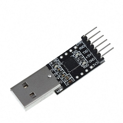
We connect the TXD legs to the RXD, and the RXD to the TXD, we do the common ground, but we do not use, as it seemed, a convenient output of 3.3 V on the adapter. In most cases, ESP8266 will drop it completely. Therefore, we feed it separately. Then we transfer ESP to the programming mode (GP0 to the ground, if anyone has forgotten) and run NODE MCU PyFlasher .

Most importantly, do not forget to erase the flash memory (yes, wipes all data), otherwise, depending on the firmware version, after programming, unnecessary garbage may remain in the memory, which in turn will pour garbage into the console during further work. Before that, I used software, where there was no option to erase pre-memory, it was terribly painful, since nothing worked. And the casket just opened, only the truth is on the English-speaking forum of the creators of NODE MCU.
Having gotten the necessary firmware, we can now write and debug programs in the LUA language (MicroPython is still there, but I did not use it) using very convenient APIs from NODE MCU. Run the previously mentioned ESPlorer.
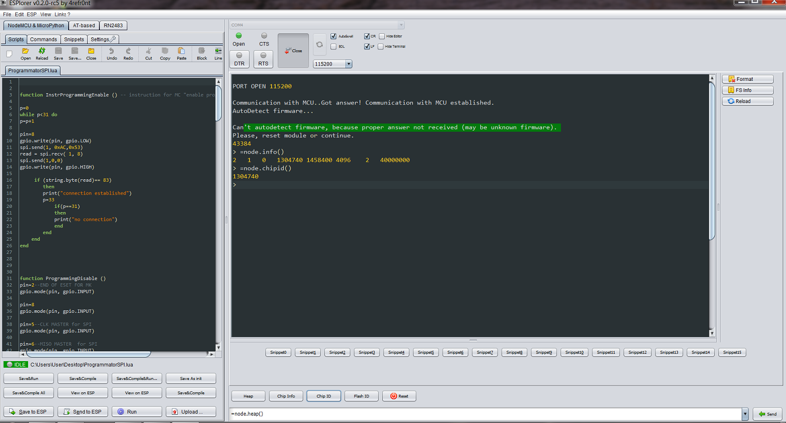
We also configure it to work with ESP8266, set the parameters of the serial connection. Everything is quite simple and repeatedly stated on the Internet.
Now we write the program on LUA, which we then load into ESP8266:
Where the relevant functions perform the following actions:
function InstrProgrammingEnable () - puts the microcontroller into the programming mode by a special command sent via SPI.
function ProgrammingEnable () - just reset the AVR for 25 ms before starting programming
function ProgrammingDisable () - after the end of programming, we translate the SPI pins into ESP8266 into an inactive state so that they do not interfere with us when executing the code on the microcontroller (all of a sudden they are used there)
function InstrFlashErase () - overwrite the flash memory on the microcontroller before programming. Why it is necessary to explain it is not necessary.
function InstrStorePAGE (H, address, data) - this command writes a program byte to the internal buffer of the microcontroller. But this is not the flash record itself, since the flash is written here page by page 128 bytes.
function InstrWriteFLASH (page_address_low, page_address_high) - and this is already a flash record and it takes time, pay attention to the time delay of 5 000 μs.
function Programming (payload) is the largest and most important function using the functions listed above. It takes the transmitted program in chunks of 1024 bytes, divides them into baytik and forms addresses for them, and then sends it to the microcontroller in the internal buffer and after every 128 bytes it initializes the flash record. Then he takes the next kilobyte of code and repeats the operation, naturally with an offset in the addresses in order to write further and not overwrite the recorded one. At the beginning, I tried to send programs as a whole, but when 6 kilobytes are exceeded in ESP8266, the available memory just ends and it crashes. One kilobyte turned out to be the most convenient unit, because it is neatly divided into parts and conveniently transmitted via TCP (we still need to get it from the computer). The larger size is also not needed, TCP, you know, in the current version limits the transmitted packet, to 1500, what is a byte (but for some reason I had 1440 transmitted, sort of).
As if nothing complicated, but several pitfalls had to be overcome.
Next comes MAIN BLOCK. In it we:
We are registering in a wireless network.
First we create a TCP server that listens to three commands:
1. “program” (we will program)
2. “data” (we will change the data)
3. "stop" (all stop).
If we program, we first initialize the SPI and create another TCP server that seizes the data (the code of the program being patched) left the byte and calls the microcontroller's programming functions for them. I understand that it looks silly to create a second server, but this is a necessity, because the local API supports the creation of only one socket, and we need to separate the “program” and “data” commands with the transmitted data, because they don’t differ, there are bytes and bytes here.
If we do not want to program, but exchange data, sending it in our case to the microcontroller, then we first send the “data” string via TCP. In response, a UDP server will be created (I remind you that we control the dynamic mechanical hand and we do not need delays in the formation of TCP packets, and generally send one byte with the whole TCP frame moveton). And UDP datagrams will be small and formed quickly.
After the UART is initialized, each byte received wirelessly is sent via a TXD wire to the microcontroller, which is required, if the corresponding program is flashed there, to accept it. Data exchange in another direction is also not difficult to organize, but I have not yet implemented it.
Well, at the “stop” command, the above-mentioned servers (except the very first one) close the connections and the main server again goes into the waiting state of the “program” and “data” commands.
Since the SPI interface is software emulated in ESP8266, I / O ports for CS, CLK, MISO, MOSI, RESET (for AVR) signals, you can use any available ones, not the ones shown in my bootloader. In addition, it turned out that, in principle, CS and MISO can also be cut off in this case, it will work without them. Well, one output is activated on the LED built into the ESP8266 board, so that it sometimes blinks and shows that the program is still alive.
There are no checks for write errors (with the exception of the first request to the AVR, but this information is simply output to the console), the EEPROM is not programmed, more than 32 KB is not sewn - in short, there is more work to do. The SPI exchange rate is about 115 Kbps, in a few seconds everything is stitched, approximately, like an ordinary sequential programmer like ISP500).
Take the code, enter your networks and passwords, compile on ESplorer, call it “init” (to start at restart) and send to ESP8266. Should work. In a sense, to work as a wireless programmer, at least.
We will now deal with the managing party - a personal computer.
In fact, we need to take the file of the HEX format, into which your programs are written, written in the ATMEL STUDIO environment and sent via WI-FI to the known port of the socket (in this case 4000). A small snag is that we need a binary BIN file for transfer, and ATMEL STUDIO pleases us only with HEX. There are two ways out; or convert it to the BIN format with a special program converter, such as WinHex, or do it yourself in your program. I haven’t done it yet, but it seems it’s not difficult, there you have to cut off the title and do something else.
As a result, I wrote the loader program in JAVA (mainly because I am not able to do anything else), working in simply beautiful and free IntelliJ IDEA. It creates a TCP client that searches for a server running on ESP8266. If it finds it, it contacts it and sends it a file located at such an address. Code below.
Here, of course, superfluous, all sorts of ready, in principle are not needed. If TCP connection is established, it is established. The only problem was that the file did not want to go in even chunks of 1024 bytes, as I really needed, although I clearly indicated the size. Apparently there is some kind of final buffer unavailable from JAVA, and it sends packets the size it wants, which is completely unacceptable for the receiving side. At first I tried to make a delay so that the buffer got tired of waiting for the next pieces and sent as is. But the delay began to work when it reached 10 seconds, which somehow seemed a bit too much for one transmitted kilobyte.
But then I noticed that for some reason the first piece always goes straight, which one was ordered, and already from the second one unpredictable bacchanalia begins. So I made the client open the connection, send a 1024 byte piece of code, and close the connection. And so until the entire file is sent. Everything worked well.
The only thing to start is to put the JAVA runtime on the computer. But I usually start right away from IntelliJ IDEA because there you can always see what is happening in the console (but JAVA is also needed here). Although, of course, in a clever way, you need to make a GUI. That is, the window where the file path falls out, the ability to change the port numbers in the same window and other necessary things. And collect all this in the form of an executable file.
And tapericha, as Koroviev used to say, we will return the citizens, to the mechanical limb MechArm itself, which was mentioned at the very beginning. We now have the ability to program it remotely and then manage it. We turn to the control program on the side of the microcontroller.
In this case, we need to control four servos. Here are these.
Such a drive is controlled by rectangular pulses, with a period of 20 ms (50 Hz) with a fill factor from 2 to 4 percent. That is, 2% is a complete turn in one direction, 4% in the other. The task is just for the AVR PWM built into it.
One servo is used to move left and right; the second on oneself - from oneself third up and down; the fourth is the claw itself, which must be compressed and unclenched. Everything is written in C and compiled to a HEX file in ATMEL STUDIO. A little strange kind of program is connected with the fact that initially the hand was controlled from the keyboard tied with wires to the microcontroller. But yesterday's wire, you need to evolve further.
Of course you can use sketches for servos from “ARDUINO”, but I didn’t like them. Most interesting to write. In addition, all four servos must operate simultaneously, and not in multiplexed mode, when the PWM switches to each servo in turn. For no one has canceled gravity, and a raised limb will instantly descend if control pulses no longer come to the corresponding servo. I'm not sure that the “ARDUINO” sketch provides simultaneous operation for four servos. But we ourselves can easily write a program that meets the necessary requirements. And in general, in the absence of an operating system that separates the lambs from the goats, using sketches of microcontroller competing for peripheral devices (and we don’t even know in advance what it is) is too productive.
Here is the code that we write to the Arduino Nano using the ESP8266-07.
The essence of the program is clear from the text and comments. We use the T1 counter for a 20 ms exemplary period and the T0, T2 counters to issue PWM signals to the four lines of the I / O port, since each of these two meters can work on two devices.
The program establishes the initial positions of the servos, through the loading of the counting registers OCR0A, OCR0B, OCR2A, OCR2B. Constant limiters are also introduced, since we do not always need a 180 degree span. Well and further, on interruption from UART, the program catches the number sent by ESP8266 (from 1 to 8) and translates it into a command for the corresponding servo drive. There are four drives, each working in two directions, so there are enough integers from one to eight. As soon as the number is selected, the contents of the aforementioned meter registers are either incremented or decremented, respectively, changing the duty cycle of the control pulse and the angle of rotation of the selected servo drive. Those drives that we did not choose, retain the old value of the angle of rotation (since the contents of the corresponding registers, although updated, but did not change) and continue to hold the mechanical arm in the same position.
Now we just have to write a control program, sorry for tautology, to control the mechanical arm directly from the computer via WI-FI.
The code is also written in JAVA, but a bit refined. A GUI appeared and the ability to edit port numbers and the network address of ESP8266.
What happens there is clear from the window. I don’t cite the text of the program here (it is available on the Github ), for the following reason: about 95% of its volume is window creation and keyboard signal processing. But the essence is the same as the previous program in JAVA. A client is created, only UDP, which, depending on the key pressed, sends a number from 1 to 8 to the specified address on the specified port.
Or you can immediately get the executable file from here . For 64 bit machines with Windows. Even the installed JAVA environment is not necessary. Everything is up with 178 MB.
So, the mechanical pen was assembled, debugged and presented to the brother for the anniversary. Can raise plastic stacks with vodka, via Skype from another city. Although for the mechanical hand of Howard Volovits from the series “The Big Bang Theory”, she is still far away.
But in the following articles (if anyone is interested) we will be able to manage it from a mobile phone, do the same with a four-wheeled robotic cart and update the time in the electronic clock from the watch servers on the Internet. Then we will put an old smartphone on a cart and we will drive a video from it onto a neural network with pattern recognition, and the control signals back to the motors,oh, something already carries me ...
And all this with the help of the beautiful ESP8266.
I would be glad if someone article seemed interesting.
[1] Pinout and specifications for ESP8266
[2] Connecting ESP8266. Fast start.
[3] NodeMCU firmware update via the cloud
[4] NODE MCU PyFlasher
[5] ESPlorer - IDE for ESP8266
[6] C programming for AVR
[7] Review of articles - “Programming microcontrollers in C”
[8] Description of NodeMCU API
[9] Lua Reference
[10] Lua scripts and modules
[11] IntelliJ IDEA
[12] Download Java to your desktop now!
[13] Atmel Studio
But all these various amateur handicrafts require, naturally, preliminary programming. And in the future with various improvements, I constantly have to reflash these crafts. It is clear that it is more convenient to do it remotely than to constantly carry them to the usual programmer. In general, thanks to the same Arduino platform, there are a lot of options here: Bluetooth, ZigBee, a radio channel with your personal protocol, IR, and even Wi-Fi. All of them allow you to establish a wireless contact with your microcontroller. But we will focus on the latest version. There are four main reasons:
1: modern, internet of things!
2: there is a wireless router in each apartment, register your devices in the home network and voila!
3: Your crafts make a revolutionary leap in their development; Not only can they be programmed at a distance, they can now also communicate with the world around them: the electronic clock independently takes the exact time from the NTP servers, the actuators are controlled from the other end of the city or country, the recording devices store the accumulated data in cloud etc. etc.
4: There is a wonderful series of ESP8266 chips on which
Further, in this article, using the example of a mechanical hand on servo drives, remote programming and data exchange with a PC (or whatever) with AVR microcontroller devices will be disassembled and demonstrated. Immediately I want to note that all the programs listed below are purely demonstration and do not have any commercial value. Therefore, claims, such as why the programmer is so castrated and little functional, or why there are no additional services that are everywhere, are not accepted. Since the codes are open, anyone can finish them on their own, for work, as long as there are enough of them.
It is assumed that the reader is already familiar with the “Arduino” modules (shields) and with the connection and firmware of ESP8266. In fact, a huge amount of materials explaining the basics of working with these devices has been posted on the Web and I would not like to repeat here. For beginners at the end of the article there is a list of useful links on these issues, where you can find a lot of information
1. Bad contacts. Since the “Arduino” shields imply switching with each other through the wires like “papa-mama”, and not through soldering, then very often something, somewhere, yes moves away. Check. And in general, as they say, electronics is the science of contacts.
2. Problems with nutrition. Do not supply 5 volts of power to where required 3.3. Sometimes from ESP8266 from this comes smoke. Although on the other hand the logical signals from the five-volt devices, it digests without problems.
3. Problems with sufficient power supply. ESP8266 has a vile nature and can sometimes consume almost three hundred milliampere, although it could have been satisfied with thirty before. Correspondingly, the sickly 3.3 volt stabilizer of the Arduino board, to which you are no doubt confused, was hooked up and immediately dropped to microscopic values. And you can not understand why it works, then no.
4. Confusion with the findings. Always check which signals go where. The RXD receiver must connect to the TXD transmitter, as well as the TXD to RXD, but the MOSI must connect to the MOSI, and the MISO to the MISO, and so on.
5. Do not count on in-circuit pull-up resistors in ESP8266, always pull the leads to zero or power, after 5-10 kilohm external resistors, and not just a jumper. Otherwise, you can at best get unprecedented current consumption, and then smell the unpleasant smell of burning plastic.
6. Shoals of software. Since the software for individual users is written by the same enthusiasts, then periodically glitches of the firmware itself and bugs when updating versions of the same firmware. It is treated by crawling on the appropriate forums, sometimes even in English. Some comrades even claimed that the ESP microcircuit itself is damp as the weather in St. Petersburg, but on the other hand there is also the opinion that since 2014 (the year of its first release) the situation has drastically improved (unlike the weather).
7. Mysterious glitches. This is a rare but nerve-consuming phenomenon. For example, for me, one “Arduino” device did not remotely sew. Rather, it was but with errors. But it was done without errors, if a loop from the programmer was hanging on it (but without the programmer itself). “AHA,” I said to myself and soldered a 15 pF capacitor between the data output and the sync output. It all worked. But the day is killed.
So let's start with the simplest. We have a mechanical limb MechArm (but not such as Howard Volovits collected) made in China and a personal computer with Windows. The task is remote firmware installation and management from a computer.
For the controlling controller, take the cute Arduino Nano miniature scarf with the ATmega328P stone. This board is perfectly crammed into a mechanical arm.
Now we will define how we will program it. There are three main ways most suitable for remote firmware: through the SPI interface, through the built-in loader, through the JTAG port.
The easiest option is of course the built-in bootloader (bootloader). This is a pre-written FLASH memory, a program that receives a code according to a certain protocol (say, by the simplest UART) and writes it to the location of the loaded program using special commands. This is how the ARDUINO IDE bootloader, for example, works. After a reset or start, the loader waits for a while for the data to be received and if it does not wait, it starts the execution of the program from the zero address. If the data arrives, he writes them to the program section. After the next reset, the loaded program starts to run. In detail, perhaps, I described inaccurately, but the essence is this. As a result, we need only three outputs for programming: an RTD receiver, a RESET reset, and GND ground. In general, the TRD transmitter is also used to verify the recorded program, but for simple demonstration applications (not for a nuclear power plant), the test can be omitted.
The loader itself is written in assembly language, there are examples of simple loaders in datasheets on AVR. You can dig out the existing loader, if it is in the public domain and just use it in the finished form, if you know the protocol for which it works. The only caveat is that this requires setting the AVR into a special mode, by flashing special fusion bits, which is done by a regular programmer, and then they can also sew the bootloader into the microcontroller’s memory (that is, it will not do without the programmer once).
The second option is SPI serial programming. There is no internal loader here, but we program by sending special commands and then data via the above interface. Here we have an external loader, but you still need to write it. When transferring, in addition to RESET and GND, there are already four additional outputs MOSI, MISO - data, SLK synchronization, CS - chip selection. But in general, you can also remove MISO and CS. The data will only be accepted (there will be no verification of the program), and we have only one crystal anyway.
Each approach has its pros and cons (and I did not consider JTAG at all, since human life is short). But in the end I was inclined to SPI because I was too lazy to write on an assembler, but I did not find any open boot loaders (I just didn’t search well).
To build a wireless channel, I, as already mentioned, chose the extremely well-known ESP8266 microcircuit, the microcontroller, or rather the whole SoC (System-on-Chip) of the Chinese manufacturer Espressif with Wi-Fi interface. In addition to Wi-Fi, it is distinguished by the ability to execute programs from an external flash memory. Specifically, for my project, I took ESP8266-07 with 512 KB of memory on board.
In general, any ESP8266 is suitable where there are extra legs for implementing SPI. Therefore, the simplest ESP8266-01 does not suit us, since it has very few legs for I / O ports. But on the other hand, the difference in price for them is less than one hundred rubles, and they are equally available. Well, large debugging boards with ESP, where, for convenience, a bunch of peripherals are divorced, we also don’t fit, because they don’t get in, where we want to shove them, into our mechanical arm.
The global essence of the idea in general was as follows. From the computer to the ESP without wires via WI-FI (within your home network) the body of the program loaded into the microcontroller is transmitted. And ESP already by wire using the SPI interface writes this program directly to the flash memory of the microcontroller. Then it naturally drops it and allows the loaded program to run. In addition, there should be an independent unit in ESP, which also manages the data exchange with the microcontroller, since we want not only to program, but also to exchange data with it. In particular, for the project with MechArm, after recording the program, we still transmit the servo control signals in order to put this hand in motion. Therefore, on ESP itself, it is desirable for us to raise a TCP server for transmitting a program and a UDP server for managing MechArm. Accordingly, these servers join the home network and carefully listen to whether there are any people willing to upload new code to MechaArm or wave to someone.
So, I found on the web, firmware already allowing to program AVR over the air, but the main problem is that for what other this firmware cannot be used anymore. And we would like after programming and communicate with the AVR also remotely.
What software we will use:
For the PC, I wrote everything in JAVA, the IntelliJ IDEA environment. But in principle, it is possible on anything, the main thing for us is to write a client who will send a program for AVR firmware to ESP8266.
I write the programs for AVR in ATMEL STUDIO , in C, rarely in assembler. I don’t use Arduino sketches in principle; almost any library I need is written another hour, with a full understanding of its work. I tried the sketches, but as long as you do not have an operating system on the AVR, the sketches will still take the peripherals from the friend and regularly fail. Yes, the IDE Arduino itself, compared with ATMEL STUDIO, of course, the thing is very primitive. But here the question is, of course, controversial, humanities and schoolchildren will be more fun and easier, probably, with sketches.
For programming ESP8266, I used the NodeMCU firmware, and I wrote programs in the Lua language. No, I would love to write in Java and C, but they are not on ESP. Lua language as applied to our task is not difficult, to master it a couple of trivia. And actually to download programs and debug them on ESP, I took the IDE ESPlorer . Domestic free product (but you can make donation to the author), which of course cannot be compared with the media mentioned above, but as they say, a gift horse ... But in order to use ESPlorer and write on LUA, we first need to change the basic firmware (supplied from the manufacturer) on the ESP8266 chip new. In this enterprise, the NODE MCU PyFlasher program will help us. In a sense, help her reflash. And we ourselves will create the firmware itself and get it into the hands of the creators' site: NodeMCU . For more information about this process you can read here:
Everything is very accessible and understandable. We add SPI support and bit operations to the base libraries (in our case, the LUA bit operations are overloaded and there is little use for them). A lot of libraries should not be pushed into the firmware, since, due to the presence of all sorts of different software, there is very little memory left on the ESP8266, some miserable 20 KB.
Of course, you can just take the finished firmware, of which there are already a lot of dangles on the Internet, but I do not recommend it. If only because some do not support bit operations (and we need them) and there is no control over the speed of data transmission via SPI.
Accordingly, they are transmitted by default at a speed of 40 MHz divided by some small factor and therefore AVR does not have time to digest them.
Who is too lazy to create firmware, you can download mine from the cloud .
Now we have the firmware and we need to load it into ESP8266 instead of the base one. For this we need a simple USB - UART adapter.
We connect the TXD legs to the RXD, and the RXD to the TXD, we do the common ground, but we do not use, as it seemed, a convenient output of 3.3 V on the adapter. In most cases, ESP8266 will drop it completely. Therefore, we feed it separately. Then we transfer ESP to the programming mode (GP0 to the ground, if anyone has forgotten) and run NODE MCU PyFlasher .
Most importantly, do not forget to erase the flash memory (yes, wipes all data), otherwise, depending on the firmware version, after programming, unnecessary garbage may remain in the memory, which in turn will pour garbage into the console during further work. Before that, I used software, where there was no option to erase pre-memory, it was terribly painful, since nothing worked. And the casket just opened, only the truth is on the English-speaking forum of the creators of NODE MCU.
Having gotten the necessary firmware, we can now write and debug programs in the LUA language (MicroPython is still there, but I did not use it) using very convenient APIs from NODE MCU. Run the previously mentioned ESPlorer.
We also configure it to work with ESP8266, set the parameters of the serial connection. Everything is quite simple and repeatedly stated on the Internet.
Now we write the program on LUA, which we then load into ESP8266:
Lua loader for AVR, recorded in ESP8266
<b>function InstrProgrammingEnable () -- instruction for MC "enable programming"</b> p=0 while p<31 do p=p+1 pin=8 gpio.write(pin, gpio.LOW) spi.send(1, 0xAC,0x53) read = spi.recv( 1, 8) spi.send(1,0,0) gpio.write(pin, gpio.HIGH) if (string.byte(read)== 83) then print("connection established") p=33 if(p==31) then print("no connection") end end end end <b>function ProgrammingDisable ()</b> pin=2--END OF ESET FOR MK gpio.mode(pin, gpio.INPUT) pin=8 gpio.mode(pin, gpio.INPUT) pin=5--CLK MASTER for SPI gpio.mode(pin, gpio.INPUT) pin=6--MISO MASTER for SPI gpio.mode(pin, gpio.INPUT) pin=7--MOSI MASTER for SPI gpio.mode(pin, gpio.INPUT) end <b>function ProgrammingEnable ()</b> pin=2-- RESET FOR MK gpio.mode(pin, gpio.OUTPUT) gpio.write(pin, gpio.LOW) pin=2--POZITIV FOR 4MSEC RESET FOR MK gpio.mode(pin, gpio.OUTPUT) gpio.write(pin, gpio.HIGH) tmr.delay(4) gpio.mode(pin, gpio.OUTPUT) gpio.write(pin, gpio.LOW) tmr.delay(25000) end <b>function InstrFlashErase() </b> pin=8 gpio.write(pin, gpio.LOW) spi.send(1,0xAC,0x80,0,0) gpio.write(pin, gpio.HIGH) tmr.delay(15000) pin=2--RESET FOR MK gpio.mode(pin, gpio.OUTPUT) gpio.write(pin, gpio.HIGH) tmr.delay(20000) gpio.write(pin, gpio.LOW) print( "FLASH is erased") InstrProgrammingEnable () end <b>function InstrStorePAGE(H, address, data)</b> pin=8 gpio.write(pin, gpio.LOW) spi.send(1,H,0,address,data) gpio.write(pin, gpio.HIGH) tmr.delay(500) end <b>function InstrWriteFLASH(page_address_low,page_address_high)</b> pin=8 gpio.write(pin, gpio.LOW) spi.send(1,0x4C,page_address_high,page_address_low,0) gpio.write(pin, gpio.HIGH) tmr.delay(5000)-- end <b>function Programming (payload)</b> pin=8--CS MASTER for SPI gpio.mode(pin, gpio.OUTPUT, gpio.PULLUP) pin=4--LED LIGHTS ON LOW gpio.mode(pin, gpio.OUTPUT) gpio.write(pin, gpio.LOW) print(string.len(payload)) page_count = 7 -- 1 for k =0 ,page_count ,1 do--quantity of pages for i=0 , 127, 2 do-- -1 address = i/2 data=payload:byte(i+1+128*k) if data == nil then data = 0xff end InstrStorePAGE(0x40,address,data) -- tmr.delay(100)-- otherwise not in time write data =payload:byte(i+1+1+128*k) if data == nil then data = 0xff end InstrStorePAGE(0x48,address,data) -- tmr.delay(100) end page_address_low=bit.band(k ,3)*64 -- 3 11 page_address_high=k/4+frame1024*2 tmr.delay(1000) InstrWriteFLASH(page_address_low,page_address_high) tmr.wdclr() end pin=4--LED gpio.mode(pin, gpio.OUTPUT) gpio.write(pin, gpio.HIGH) end <b>--MAIN BLOCK</b> wifi.setmode(wifi.STATION) --wifi.sta.config(" ","") -- set SSID and password of your access point station_cfg={} tmr.delay(30000) station_cfg.ssid=" " tmr.delay(30000) station_cfg.pwd="" tmr.delay(30000) wifi.sta.config(station_cfg) tmr.delay(30000) wifi.sta.connect() tmr.delay(1000000) print(wifi.sta.status()) print(wifi.sta.getip()) while ( wifi.sta.status()~=1 ) do if( wifi.sta.status()==5) then break end end sv=net.createServer(net.TCP,30) tmr.delay(100) print("SERVER READY") sv:listen(4000,function(c) c:on("receive", function(c, payload) print(payload) if (payload =="program\r\n") then c:send("ready\r\n") print("ready for program\r\n") spi.setup(1, spi.MASTER, spi.CPOL_LOW, spi.CPHA_LOW, spi.DATABITS_8,320,spi.FULLDUPLEX) ProgrammingEnable () tmr.delay(100) InstrProgrammingEnable () tmr.delay(100) InstrFlashErase() tmr.delay(100) frame1024=0-- st=net.createServer(net.TCP,30) st:listen(4001,function(c) c:on("receive", function(c, payload) tmr.wdclr() Programming (payload) frame1024=frame1024+1 end) end) end if (payload =="data\r\n") then c:send("ready\r\n") print("ready for data\r\n") srv=net.createServer(net.UDP) tmr.delay(1000) pin=10 gpio.write(pin, gpio.HIGH) uart.setup(0,9600,8,0,1,0) srv:listen(5000) srv:on("receive", function(srv, pl) pl=pl*1 --print(pl) uart.write(0,pl) tmr.wdclr() end) end if (payload =="stop\r\n") then if(st~=nil) then st:close() frame1024=0 ProgrammingDisable () print("stop program") end if(srv~=nil) then srv:close() print("stop data") end end end) end) end)
Where the relevant functions perform the following actions:
function InstrProgrammingEnable () - puts the microcontroller into the programming mode by a special command sent via SPI.
function ProgrammingEnable () - just reset the AVR for 25 ms before starting programming
function ProgrammingDisable () - after the end of programming, we translate the SPI pins into ESP8266 into an inactive state so that they do not interfere with us when executing the code on the microcontroller (all of a sudden they are used there)
function InstrFlashErase () - overwrite the flash memory on the microcontroller before programming. Why it is necessary to explain it is not necessary.
function InstrStorePAGE (H, address, data) - this command writes a program byte to the internal buffer of the microcontroller. But this is not the flash record itself, since the flash is written here page by page 128 bytes.
function InstrWriteFLASH (page_address_low, page_address_high) - and this is already a flash record and it takes time, pay attention to the time delay of 5 000 μs.
function Programming (payload) is the largest and most important function using the functions listed above. It takes the transmitted program in chunks of 1024 bytes, divides them into baytik and forms addresses for them, and then sends it to the microcontroller in the internal buffer and after every 128 bytes it initializes the flash record. Then he takes the next kilobyte of code and repeats the operation, naturally with an offset in the addresses in order to write further and not overwrite the recorded one. At the beginning, I tried to send programs as a whole, but when 6 kilobytes are exceeded in ESP8266, the available memory just ends and it crashes. One kilobyte turned out to be the most convenient unit, because it is neatly divided into parts and conveniently transmitted via TCP (we still need to get it from the computer). The larger size is also not needed, TCP, you know, in the current version limits the transmitted packet, to 1500, what is a byte (but for some reason I had 1440 transmitted, sort of).
As if nothing complicated, but several pitfalls had to be overcome.
Next comes MAIN BLOCK. In it we:
We are registering in a wireless network.
First we create a TCP server that listens to three commands:
1. “program” (we will program)
2. “data” (we will change the data)
3. "stop" (all stop).
If we program, we first initialize the SPI and create another TCP server that seizes the data (the code of the program being patched) left the byte and calls the microcontroller's programming functions for them. I understand that it looks silly to create a second server, but this is a necessity, because the local API supports the creation of only one socket, and we need to separate the “program” and “data” commands with the transmitted data, because they don’t differ, there are bytes and bytes here.
If we do not want to program, but exchange data, sending it in our case to the microcontroller, then we first send the “data” string via TCP. In response, a UDP server will be created (I remind you that we control the dynamic mechanical hand and we do not need delays in the formation of TCP packets, and generally send one byte with the whole TCP frame moveton). And UDP datagrams will be small and formed quickly.
After the UART is initialized, each byte received wirelessly is sent via a TXD wire to the microcontroller, which is required, if the corresponding program is flashed there, to accept it. Data exchange in another direction is also not difficult to organize, but I have not yet implemented it.
Well, at the “stop” command, the above-mentioned servers (except the very first one) close the connections and the main server again goes into the waiting state of the “program” and “data” commands.
Since the SPI interface is software emulated in ESP8266, I / O ports for CS, CLK, MISO, MOSI, RESET (for AVR) signals, you can use any available ones, not the ones shown in my bootloader. In addition, it turned out that, in principle, CS and MISO can also be cut off in this case, it will work without them. Well, one output is activated on the LED built into the ESP8266 board, so that it sometimes blinks and shows that the program is still alive.
There are no checks for write errors (with the exception of the first request to the AVR, but this information is simply output to the console), the EEPROM is not programmed, more than 32 KB is not sewn - in short, there is more work to do. The SPI exchange rate is about 115 Kbps, in a few seconds everything is stitched, approximately, like an ordinary sequential programmer like ISP500).
Take the code, enter your networks and passwords, compile on ESplorer, call it “init” (to start at restart) and send to ESP8266. Should work. In a sense, to work as a wireless programmer, at least.
We will now deal with the managing party - a personal computer.
In fact, we need to take the file of the HEX format, into which your programs are written, written in the ATMEL STUDIO environment and sent via WI-FI to the known port of the socket (in this case 4000). A small snag is that we need a binary BIN file for transfer, and ATMEL STUDIO pleases us only with HEX. There are two ways out; or convert it to the BIN format with a special program converter, such as WinHex, or do it yourself in your program. I haven’t done it yet, but it seems it’s not difficult, there you have to cut off the title and do something else.
As a result, I wrote the loader program in JAVA (mainly because I am not able to do anything else), working in simply beautiful and free IntelliJ IDEA. It creates a TCP client that searches for a server running on ESP8266. If it finds it, it contacts it and sends it a file located at such an address. Code below.
JAVA file downloader working on the PC side
import java.io.*; import java.net.*; import java.util.ArrayList; import java.util.List; public class Net { <b> public static void main(String args[]) { new Http_client(4000); }</b> } class Http_client extends Thread { int port; String s; String Greetings_from_S; Http_client(int port){ this.port = port; start(); } public void run() { //192.168.1.113 - ESP8266 . , // , try (Socket socket = new Socket("192.168.1.113", port)) { PrintWriter pw = new PrintWriter(new OutputStreamWriter(socket.getOutputStream()),true); pw.println("program");// Greetings with SERVER System.out.println("program"); BufferedReader br = new BufferedReader(new InputStreamReader(socket.getInputStream())); Greetings_from_S = br.readLine(); System.out.println(Greetings_from_S); if(Greetings_from_S.equals("ready")) { try { File file = new File("d:BlinkOUT.bin");// BufferedInputStream bis = new BufferedInputStream(new FileInputStream(file)); byte [] data = new byte[bis.available()]; bis.read(data); byte [] data_buffer = new byte[1024]; int frames = data.length/1024; System.out.println(frames); int residy = data.length%1024; for (int i = 0; i < frames;i++) { for (int k = 0; k< (1024); k++) { data_buffer[k] = data[k+1024*(i)]; } sendingChunk(data_buffer); } byte [] data_buffer2= new byte[residy]; for (int i = 0; i < residy;i++) { data_buffer2[i] = data[i+1024*(frames)]; } sendingChunk(data_buffer2); pw.println("stop");// System.out.println("stop program"); } catch (Exception e) { System.out.println(e); } } } catch (Exception e) { System.out.println(e); } } public void sendingChunk (byte [] data_buffer){ try (Socket socket = new Socket("192.168.1.113", 4001)){ BufferedOutputStream bos = new BufferedOutputStream((socket.getOutputStream())); bos.write(data_buffer); bos.flush(); System.out.println(data_buffer.length); } catch (Exception e) { System.out.println(e); } } }
Here, of course, superfluous, all sorts of ready, in principle are not needed. If TCP connection is established, it is established. The only problem was that the file did not want to go in even chunks of 1024 bytes, as I really needed, although I clearly indicated the size. Apparently there is some kind of final buffer unavailable from JAVA, and it sends packets the size it wants, which is completely unacceptable for the receiving side. At first I tried to make a delay so that the buffer got tired of waiting for the next pieces and sent as is. But the delay began to work when it reached 10 seconds, which somehow seemed a bit too much for one transmitted kilobyte.
But then I noticed that for some reason the first piece always goes straight, which one was ordered, and already from the second one unpredictable bacchanalia begins. So I made the client open the connection, send a 1024 byte piece of code, and close the connection. And so until the entire file is sent. Everything worked well.
The only thing to start is to put the JAVA runtime on the computer. But I usually start right away from IntelliJ IDEA because there you can always see what is happening in the console (but JAVA is also needed here). Although, of course, in a clever way, you need to make a GUI. That is, the window where the file path falls out, the ability to change the port numbers in the same window and other necessary things. And collect all this in the form of an executable file.
And tapericha, as Koroviev used to say, we will return the citizens, to the mechanical limb MechArm itself, which was mentioned at the very beginning. We now have the ability to program it remotely and then manage it. We turn to the control program on the side of the microcontroller.
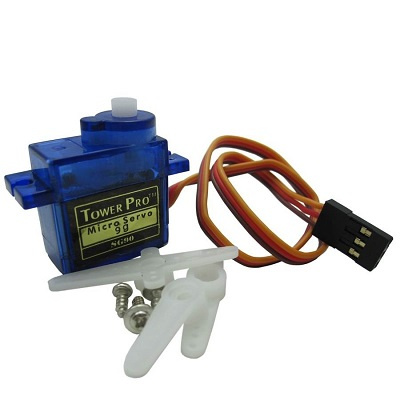
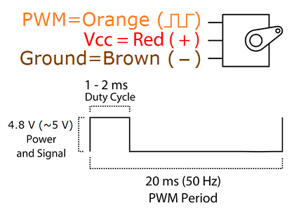
In this case, we need to control four servos. Here are these.
Such a drive is controlled by rectangular pulses, with a period of 20 ms (50 Hz) with a fill factor from 2 to 4 percent. That is, 2% is a complete turn in one direction, 4% in the other. The task is just for the AVR PWM built into it.
One servo is used to move left and right; the second on oneself - from oneself third up and down; the fourth is the claw itself, which must be compressed and unclenched. Everything is written in C and compiled to a HEX file in ATMEL STUDIO. A little strange kind of program is connected with the fact that initially the hand was controlled from the keyboard tied with wires to the microcontroller. But yesterday's wire, you need to evolve further.
Of course you can use sketches for servos from “ARDUINO”, but I didn’t like them. Most interesting to write. In addition, all four servos must operate simultaneously, and not in multiplexed mode, when the PWM switches to each servo in turn. For no one has canceled gravity, and a raised limb will instantly descend if control pulses no longer come to the corresponding servo. I'm not sure that the “ARDUINO” sketch provides simultaneous operation for four servos. But we ourselves can easily write a program that meets the necessary requirements. And in general, in the absence of an operating system that separates the lambs from the goats, using sketches of microcontroller competing for peripheral devices (and we don’t even know in advance what it is) is too productive.
Here is the code that we write to the Arduino Nano using the ESP8266-07.
Program to control MechArm for AVRmega328P microcontroller
#define F_CPU 16000000 #include <avr/io.h> #include <stdint.h>// #include <avr/interrupt.h> #include <math.h> // #include <stdio.h> // - #include <avr/eeprom.h> #include <setjmp.h> #include <stdlib.h> // #define UART_BAUD_RATE 115200 // 1 20 #define COUNTER1_OFF TCCR1B=0b00000000 // CS02 CS01 CS00 - 000 - ; 001 ; 010 c 8; 011 -64; 100 -256; 101 -1024 #define COUNTER1_ON TCCR1B=0b00000011 // 0 0 1 #define COUNTER0_OFF TCCR0B=0b00000000 // CS02 CS01 CS00 - 000 - ; 001 ; 010 c 8; 011 -64; 100 -256; 101 -1024 #define COUNTER0_ON TCCR0B=0b00000100 // 2 B2(PD6) 3(PD7) #define COUNTER2_OFF TCCR2B=0b00000000 // CS02 CS01 CS00 - 000 - ; 001 ; 010 c 8; 011 -64; 100 -256; 101 -1024 #define COUNTER2_ON TCCR2B=0b00000110 volatile uint16_t period_20ms; volatile uint8_t State_of_keyboard; volatile uint8_t start_position [6]; volatile int8_t number_servo; ISR(USART_RX_vect)// UART { State_of_keyboard=UDR0; return; } ISR(TIMER0_COMPA_vect)// 0 { PORTB &=~(1<<0); TIMSK0&=~(1<<OCIE0A); TIFR0 |=(1<<OCF0A); return; } ISR(TIMER0_COMPB_vect) // 1 { PORTB &=~(1<<1); TIFR0 |=(1<<OCF0B); TIMSK0 &=~(1<<OCIE0B); return; } ISR(TIMER2_COMPA_vect)// 2(PD6) { PORTD &=~(1<<6); TIFR2 |=(1<<OCF2A); TIMSK2 &=~(1<<OCIE2A); return; } ISR(TIMER2_COMPB_vect)// 3(PD7) { PORTD &=~(1<<7); TIFR2 |=(1<<OCF2B); TIMSK2 &=~(1<<OCIE2B); return; } ISR(TIMER1_OVF_vect){// 20 COUNTER1_OFF; COUNTER0_OFF; COUNTER2_OFF; TIFR0 |=(1<<OCF0A); TIFR0 |=(1<<OCF0B); TIFR2 |=(1<<OCF2A); TIFR2 |=(1<<OCF2B); TIFR1 |=(1<<TOV1); PORTB |=(1<<0)|(1<<1); PORTD |=(1<<6)|(1<<7); TCNT1 = period_20ms; // 20 TCNT0 = 0; TCNT2 = 0; TIMSK0|=(1<<OCIE0A)|(1<<OCIE0B); TIMSK2|=(1<<OCIE2A)|(1<<OCIE2B); OCR0A=start_position[1];// 0 0 OCR0B=start_position[2];// 0 1 OCR2A=start_position[3];// 0 2 OCR2B=start_position[4];// 0 3 COUNTER1_ON; COUNTER2_ON; COUNTER0_ON; return; } void time_delay(long i) { cli();sei(); long k; i*=2000; for(k=0;k<i;k++){;;}; } void timer_counter0_1_2_INIT()// 0,1,2 { // 1 TCCR1A &=~(1<<COM1A0)|~(1<<COM1A1)|~(1<<COM1B0)|~(1<<COM1B1);// TCCR1A &=~(1<<WGM10)|~(1<<WGM11); TCCR1B &=~(1<<WGM12)|~(1<<WGM13);// period_20ms=60575; TCNT1 = period_20ms; TIMSK1|=(1<<TOIE1);//| //TIFR0 TOV0 // 0 TCCR0A &=~(1<<COM0A0)|~(1<<COM0A1)|~(1<<COM0B0)|~(1<<COM0B1);// TCCR0A &=~(1<<WGM00)|~(1<<WGM01); TCCR0B &=~(1<<WGM02);// // 2 TCCR2A &=~(1<<COM2A0)|~(1<<COM2A1)|~(1<<COM2B0)|~(1<<COM2B1);// TCCR2A &=~(1<<WGM20)|~(1<<WGM21); TCCR2B &=~(1<<WGM22);// COUNTER1_ON; } void servo_reset() { start_position[1]=97;// 0 0 start_position[2]=70;// 0 1 start_position[3]=92;// 0 2 start_position[4]=124; // 0 3 COUNTER1_ON; time_delay(100); } void servo_go( int8_t moven, uint8_t servo_position_max, uint8_t servo_position_min)// { switch (moven){ case 1: start_position[number_servo]++; if(start_position[number_servo]==servo_position_max){start_position[number_servo]--;};// +90 break; case 2: start_position[number_servo]--; if(start_position[number_servo]==servo_position_min){start_position[number_servo]++;};//6 -90 break; }; time_delay(20); return; } //PORTB-0,1, PORTD - 6,7 - , 8- COUNTER 0 int main(void) { uint8_t servo_positionmin=0, servo_positionmax=0; int8_t const servo_position1max = 122, servo_position1min=58; // int8_t const servo_position2max = 120, servo_position2min=36;// int8_t const servo_position3max = 125, servo_position3min=68;// int8_t const servo_position4max = 129, servo_position4min=108;// 128 108 sei(); DDRD = 0B11000010; // D2-D5 , D0 RX, D1 TX, D6 D7 3 4 PORTD = 0B00111110; // DDRB |=(1<<0)|(1<<1);// PORTB &=(~1<<0)|(~1<<1); UCSR0A=0;// UART UCSR0B=0b10010000; UCSR0C=0b00000110; UBRR0L=103;// 115200 UBRR0H=0; timer_counter0_1_2_INIT(); servo_reset(); PORTB |=(1<<5); while (1) { switch (State_of_keyboard) { case 1:// 1 PD0(PB0) number_servo=1; servo_positionmin=servo_position1min; servo_positionmax=servo_position1max; break; case 2: // 1 PD0(PB0) number_servo=1; servo_positionmin=servo_position1min; servo_positionmax=servo_position1max; break; case 5: number_servo=2; // 2 PD1(PB1) servo_positionmin=servo_position2min; servo_positionmax=servo_position2max; break; case 6: number_servo=2; // 2 PD1(PB1) servo_positionmin=servo_position2min; servo_positionmax=servo_position2max; break; case 7: number_servo=3;// 3 PD6 servo_positionmin=servo_position3min; servo_positionmax=servo_position3max; break; case 8: number_servo=3;// 3 PD6 servo_positionmin=servo_position3min; servo_positionmax=servo_position3max; break; case 3: number_servo=4; // 4 PD7 servo_positionmin=servo_position4min; servo_positionmax=servo_position4max; break;// case 4: number_servo=4; // 4 PD7 servo_positionmin=servo_position4min; servo_positionmax=servo_position4max; break;// // c - , 4- // , } if(State_of_keyboard==1||State_of_keyboard==3||State_of_keyboard==5||State_of_keyboard==7) { servo_go(1,servo_positionmax,servo_positionmin);// } if(State_of_keyboard==2||State_of_keyboard==4||State_of_keyboard==6||State_of_keyboard==8) // { servo_go(2,servo_positionmax,servo_positionmin);// } time_delay(20); } }
The essence of the program is clear from the text and comments. We use the T1 counter for a 20 ms exemplary period and the T0, T2 counters to issue PWM signals to the four lines of the I / O port, since each of these two meters can work on two devices.
The program establishes the initial positions of the servos, through the loading of the counting registers OCR0A, OCR0B, OCR2A, OCR2B. Constant limiters are also introduced, since we do not always need a 180 degree span. Well and further, on interruption from UART, the program catches the number sent by ESP8266 (from 1 to 8) and translates it into a command for the corresponding servo drive. There are four drives, each working in two directions, so there are enough integers from one to eight. As soon as the number is selected, the contents of the aforementioned meter registers are either incremented or decremented, respectively, changing the duty cycle of the control pulse and the angle of rotation of the selected servo drive. Those drives that we did not choose, retain the old value of the angle of rotation (since the contents of the corresponding registers, although updated, but did not change) and continue to hold the mechanical arm in the same position.
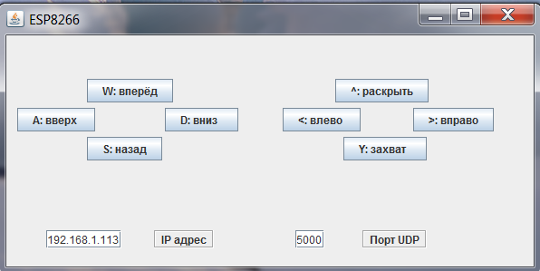
Now we just have to write a control program, sorry for tautology, to control the mechanical arm directly from the computer via WI-FI.
The code is also written in JAVA, but a bit refined. A GUI appeared and the ability to edit port numbers and the network address of ESP8266.
What happens there is clear from the window. I don’t cite the text of the program here (it is available on the Github ), for the following reason: about 95% of its volume is window creation and keyboard signal processing. But the essence is the same as the previous program in JAVA. A client is created, only UDP, which, depending on the key pressed, sends a number from 1 to 8 to the specified address on the specified port.
Or you can immediately get the executable file from here . For 64 bit machines with Windows. Even the installed JAVA environment is not necessary. Everything is up with 178 MB.
So, the mechanical pen was assembled, debugged and presented to the brother for the anniversary. Can raise plastic stacks with vodka, via Skype from another city. Although for the mechanical hand of Howard Volovits from the series “The Big Bang Theory”, she is still far away.
But in the following articles (if anyone is interested) we will be able to manage it from a mobile phone, do the same with a four-wheeled robotic cart and update the time in the electronic clock from the watch servers on the Internet. Then we will put an old smartphone on a cart and we will drive a video from it onto a neural network with pattern recognition, and the control signals back to the motors,
And all this with the help of the beautiful ESP8266.
I would be glad if someone article seemed interesting.
[1] Pinout and specifications for ESP8266
[2] Connecting ESP8266. Fast start.
[3] NodeMCU firmware update via the cloud
[4] NODE MCU PyFlasher
[5] ESPlorer - IDE for ESP8266
[6] C programming for AVR
[7] Review of articles - “Programming microcontrollers in C”
[8] Description of NodeMCU API
[9] Lua Reference
[10] Lua scripts and modules
[11] IntelliJ IDEA
[12] Download Java to your desktop now!
[13] Atmel Studio
All Articles