Telekino # 3
The previous part of the story is here .
Slowly began to work on the mechanics of the apparatus for digitizing film. For the frame I bought a quarter sheet of 12mm plywood and sawed with a manual electric jigsaw. It turned out not perfect, but rather smoothly. Donors for the mechanics were two video players traded for chocolates on a local forum.
Next a lot of photos ...
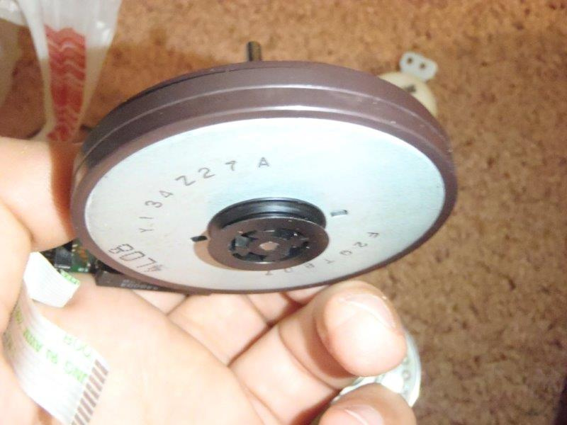
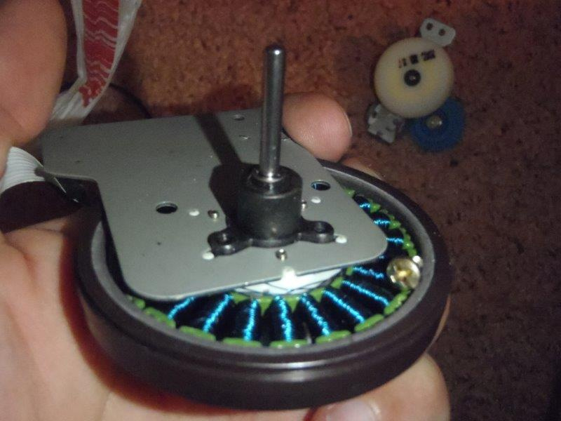
Video Head:
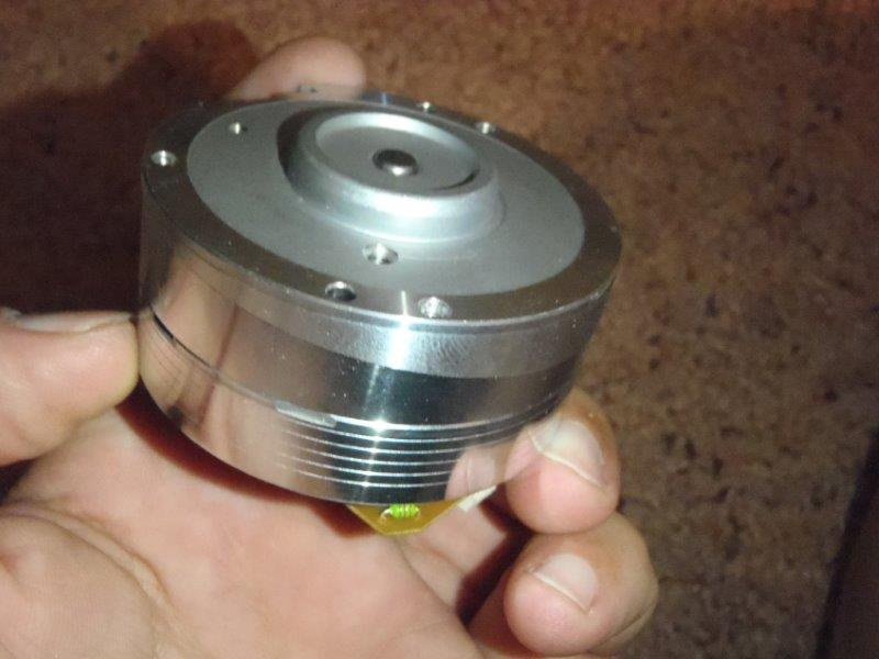
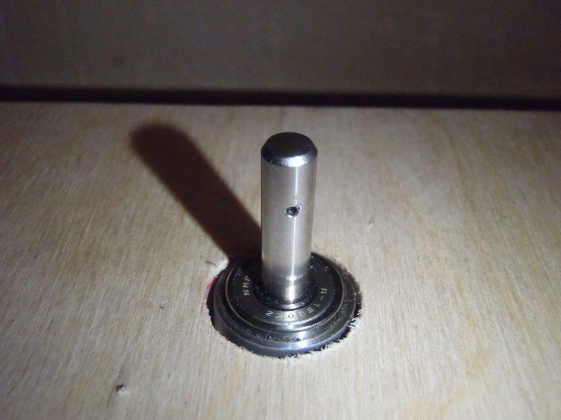
The accuracy of manufacturing pleases the eye, but the hand takes the grinder and mercilessly get rid of all the excess. As a result, we get a wonderful spindle under one of the coils.
We drill the flange and fix it on the screws, quickly and reliably. Inside the spindle there are two rather high-quality bearings.
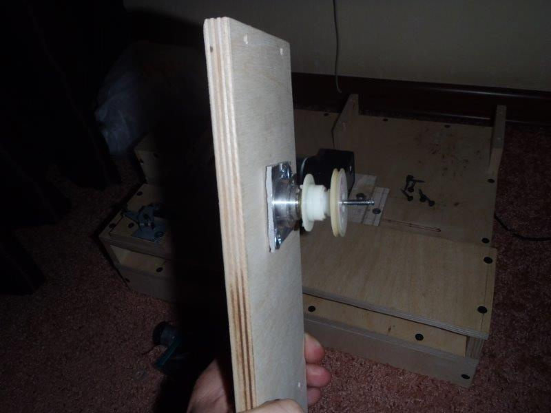
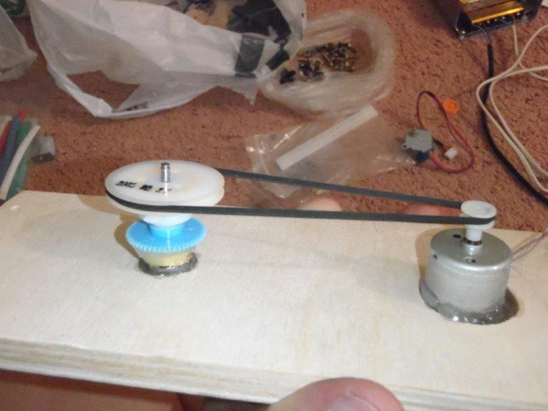
Then we make the winder drive, we need a small speed and managed to adjust the clutch from the same Vidic.
But this option turned out to be wildly noisy, even silicone lubricant did not help and had to be redone:
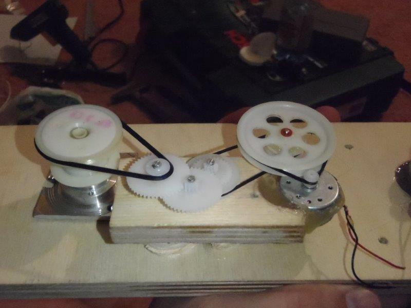
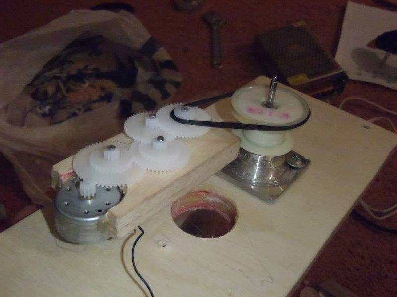
I ordered gears from the Chinese ( these and these ), the quality is not bad, there are almost no oblasts, although some had to be combined with shunts and glue.
The second viewhead turned out to be of a slightly different design, and the spindle could not be done so well from it. He took out the axle and bearings from it and put it on hot melt glue. This spindle will be for rewinding, so the design is simpler. Dvizhek, belt and clutch from Vidic, though the clutch had to glue, otherwise it gives little effort does not rewind.
And here there was one problem, the diameter of the axes of the video heads is about 4.5 mm, and under the reels with film you need 6 mm, besides, they are smooth. I tried to drill 0.8 with a carbide drill, one shaft was drilled, and the second turned out to be hot and the drill hardly takes it. So far, I have not figured out what to do with it.
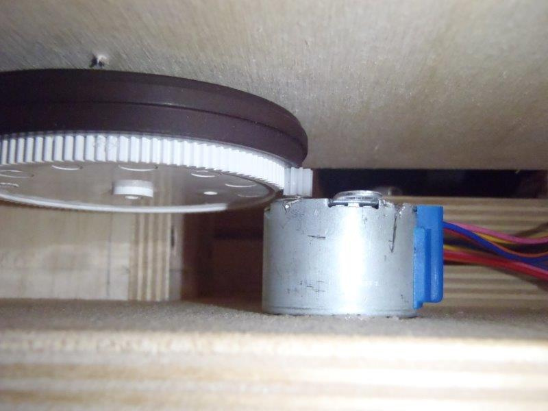
The knot of the exact broach was made from this engine, I don’t know what it is called correctly, let's call it a capstan.
All the insides of the engine were removed, the native mount with three screws was successfully used. I glued the big gear and put the stepper motor from the arduin set.
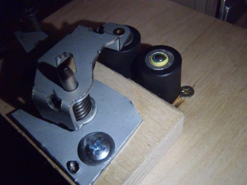
As planned broach made rubber rollers:
For the lamp, I made such a house and a film channel from aluminum strips. One lane is fixed, and the second is mobile. In terms of making it spring-loaded and coming up with a film channel cover to press the film on top. The window is twice as large as the frame so that there are no shadows.
I ordered a 20-watt LED and pick up a matte filter. An experiment with a LED flashlight showed that without a matte filter the film looks terribly scratched, and with a matte filter there are almost no scratches.
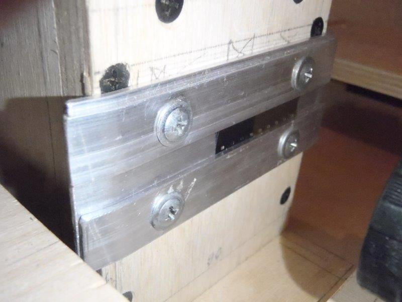
The camera is secured on a movable platform, the professional milling grooves with a hand mill, and through them the screws are screwed into a lining of the same size. Screws with a diameter less than the grooves and can be moved a couple of mm to the left and to the right.
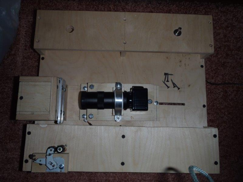
Between the upper lining of the spring, due to what you can change the tilt and height of the camera within + -5mm. The experiment showed that the setting can be done very precisely, although the upper screws can be taken with a smaller step, but there were no others without a thread in the upper part so that they would not fit tightly in the store.

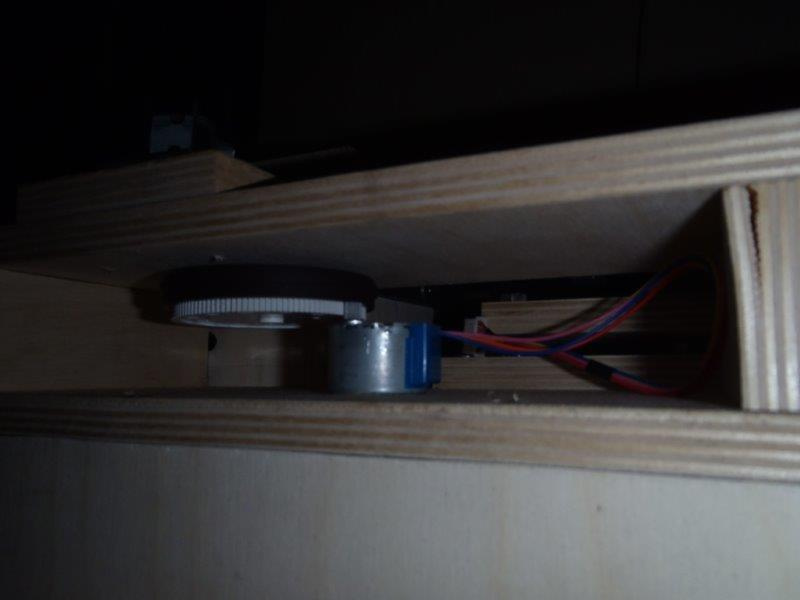
In general, it looks like this, though the photo was made before the second spindle was pasted.
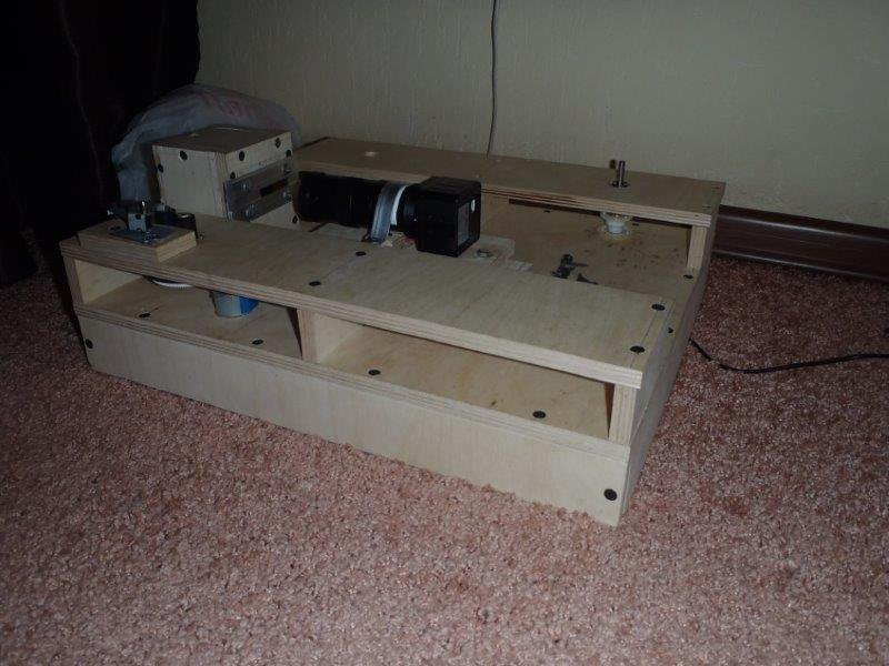
That's all for now, the mechanics are almost completed, could not resist, tucked the film and made the first frame.
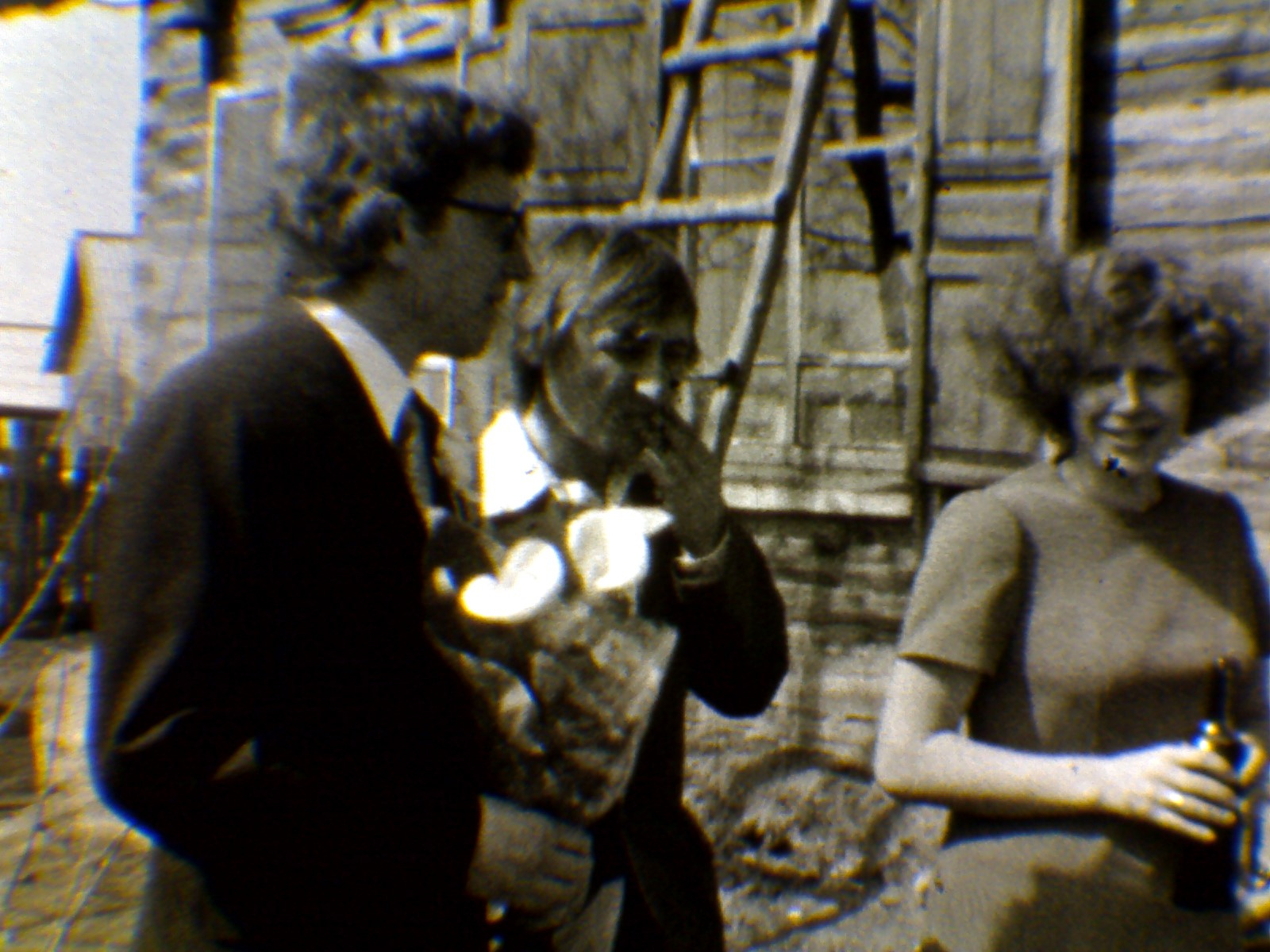
Honestly not impressed, but nothing to compare with, I hope the video will look better.
Slowly began to work on the mechanics of the apparatus for digitizing film. For the frame I bought a quarter sheet of 12mm plywood and sawed with a manual electric jigsaw. It turned out not perfect, but rather smoothly. Donors for the mechanics were two video players traded for chocolates on a local forum.
Next a lot of photos ...
Video Head:
The accuracy of manufacturing pleases the eye, but the hand takes the grinder and mercilessly get rid of all the excess. As a result, we get a wonderful spindle under one of the coils.
We drill the flange and fix it on the screws, quickly and reliably. Inside the spindle there are two rather high-quality bearings.
Then we make the winder drive, we need a small speed and managed to adjust the clutch from the same Vidic.
But this option turned out to be wildly noisy, even silicone lubricant did not help and had to be redone:
I ordered gears from the Chinese ( these and these ), the quality is not bad, there are almost no oblasts, although some had to be combined with shunts and glue.
The second viewhead turned out to be of a slightly different design, and the spindle could not be done so well from it. He took out the axle and bearings from it and put it on hot melt glue. This spindle will be for rewinding, so the design is simpler. Dvizhek, belt and clutch from Vidic, though the clutch had to glue, otherwise it gives little effort does not rewind.
And here there was one problem, the diameter of the axes of the video heads is about 4.5 mm, and under the reels with film you need 6 mm, besides, they are smooth. I tried to drill 0.8 with a carbide drill, one shaft was drilled, and the second turned out to be hot and the drill hardly takes it. So far, I have not figured out what to do with it.
The knot of the exact broach was made from this engine, I don’t know what it is called correctly, let's call it a capstan.
All the insides of the engine were removed, the native mount with three screws was successfully used. I glued the big gear and put the stepper motor from the arduin set.
As planned broach made rubber rollers:
For the lamp, I made such a house and a film channel from aluminum strips. One lane is fixed, and the second is mobile. In terms of making it spring-loaded and coming up with a film channel cover to press the film on top. The window is twice as large as the frame so that there are no shadows.
I ordered a 20-watt LED and pick up a matte filter. An experiment with a LED flashlight showed that without a matte filter the film looks terribly scratched, and with a matte filter there are almost no scratches.
The camera is secured on a movable platform, the professional milling grooves with a hand mill, and through them the screws are screwed into a lining of the same size. Screws with a diameter less than the grooves and can be moved a couple of mm to the left and to the right.
Between the upper lining of the spring, due to what you can change the tilt and height of the camera within + -5mm. The experiment showed that the setting can be done very precisely, although the upper screws can be taken with a smaller step, but there were no others without a thread in the upper part so that they would not fit tightly in the store.
In general, it looks like this, though the photo was made before the second spindle was pasted.
That's all for now, the mechanics are almost completed, could not resist, tucked the film and made the first frame.
Honestly not impressed, but nothing to compare with, I hope the video will look better.
All Articles