My experience with a laser engraver
Hi, Geektimes! Writes student ITMO Institute of the program " lasers for information and communication systems ." This summer I had a chance to work with a laser engraver. I want to share my observations on this issue and describe my work.
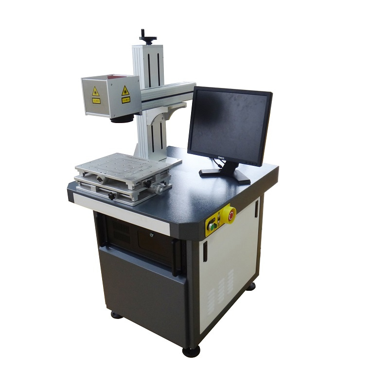
First, about the device itself - a sign on the back side says:
- Machine Name: Fiber Laser Machine
- Model: LP-FLM 50
- Manufacturer: LaserPower Technology (Suzhou) Co., Ltd.
- Power Supply: AC220V, 50 / 60hz
- Machine software - Ezcad 2.0.
Googling the model, on the first link you can find more information about it:
- Power: 50 W
- Wavelength: 1064
- Marking area: 110mmx110mm, 200mmx200mm, 300mmx300mm
- Minimum line width: 0.03 mm
- Minimum character size: ≤0.05 mm
- Marking speed: ≤7000 mm / s
- Pulse width: ≤60 micron with
- Cooling: air cooling
- Power requirement: single phase, alternating current 220V, 50 / 60Hz
Features:
The machine is equipped with a laser source with a long service life. It does not require consumables, suitable for deep engraving. High speed, accuracy and quality marking.
Application:
The laser can apply logos, symbols, serial numbers, bar codes or QR codes on metal (carbon and stainless steel, aluminum, copper, brass, zinc, etc.) and some non-metals (plastic, rubber, leather, paper and etc.).
I was offered to conduct experiments in several areas, to work out several mini-projects:
- Studying the effect of a laser when its three parameters change (power, modulation frequency, speed).
- Creating a PCB.
- Generation \ embodiment of ideas for creating products under the order.
Metal processing in different modes
I wanted to understand how the individual parameters of the laser engraver affect the depth of burning. Initially, engraving in depth didn’t go much, made many passes, reduced the step of hatching, but nothing helped. It turned out that the treated surface was simply out of focus. After adjusting the height of the radiation source, it went.
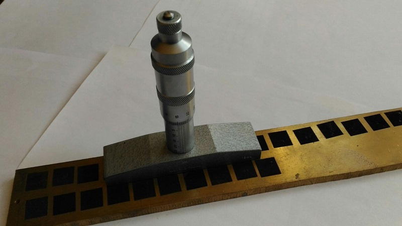
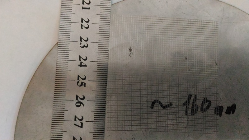
In Ezcad, I drew a square and made a triple shading. All three layers have the same pitch of 0.01 and the difference in the slope: the first layer has 0 degrees, the second one has 45 degrees, and the third one has 45 degrees.
After burning with a micrometer, the depth of the areas exposed to laser radiation was measured.
According to the results, the graphs of the dependence of the depth on the variable value (power, speed, modulation frequency) were compiled. The graphs turned out very logical:

The higher the modulation frequency, the greater the laser impact on the surface, the greater the depth.

The higher the speed of the beam, the smaller the laser's impact on the surface, which means less depth.
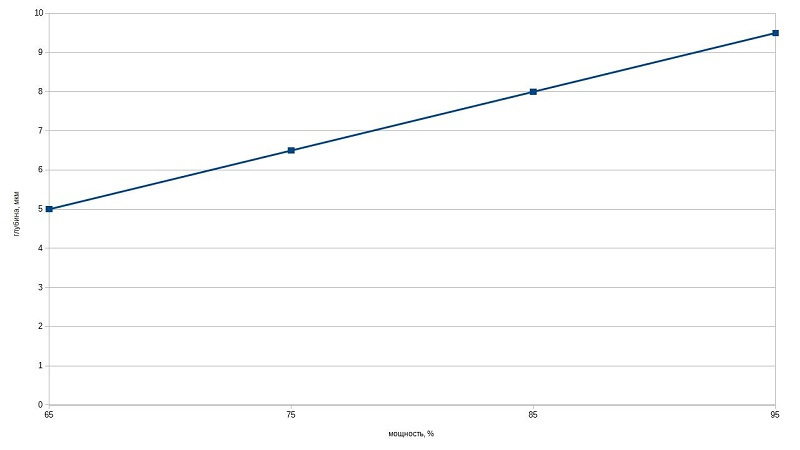
The most logical graph, the more power the deeper.
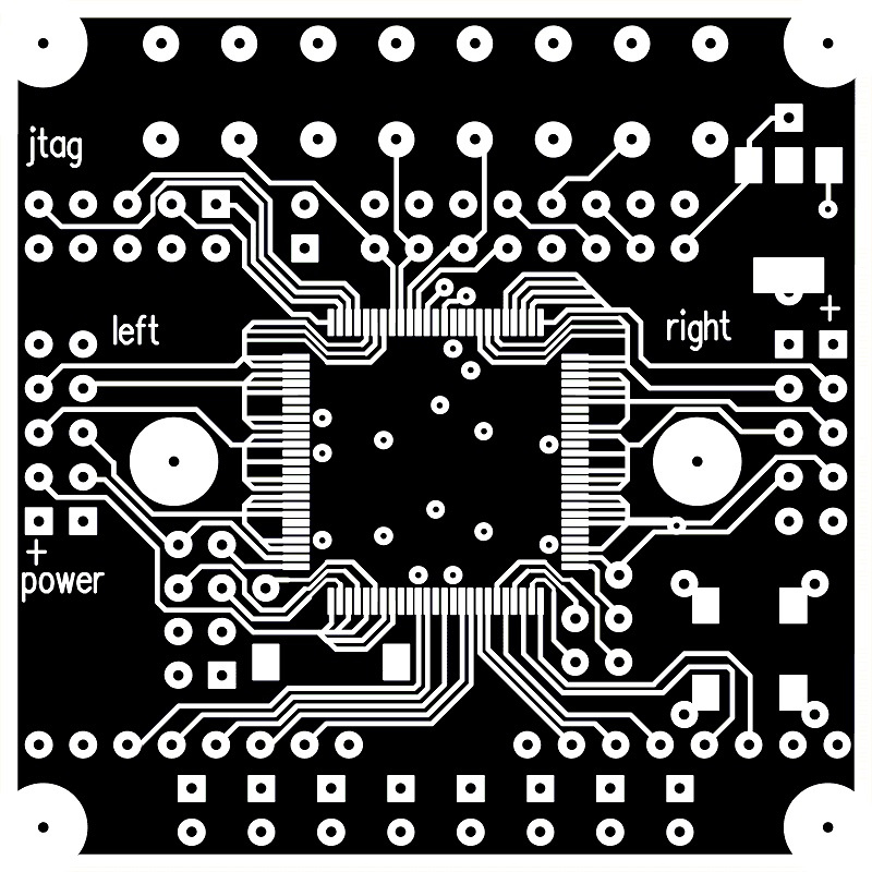
PCB creation
I decided to make a mars rover fee. To do this, created an inverse image. Bmp-format.
The original idea was to burn copper from the surface, leaving tracks. I wanted to shoot copper in layers of low power. I thought that after 5-10 passes of burning, there will be a clean getinax.
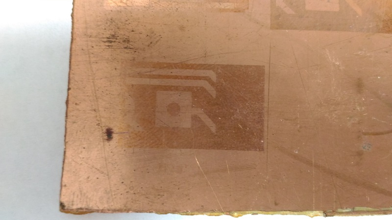
This idea had to be abandoned, since at a certain moment the foil burned when the laser was acting on copper, and the getinax began to evaporate.
There was an idea to cover the plates with paint and burn it. However, in this case, the desired manufacturability is lost, because in this case it is necessary to perform the usual operation of etching the board with ferric chloride.
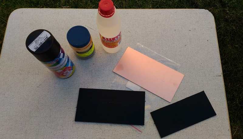
The first boards were stained.
Most likely, when the paint was evaporated, the smoke lingering over the working surface scattered the beam. During the second pass, no trace was left of the stains.
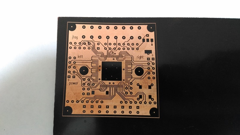
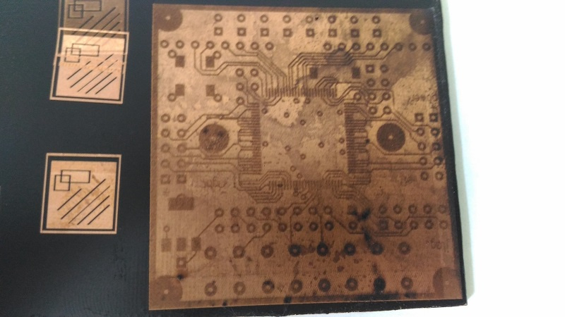
However, here we were waiting for the next problem, hidden in the design of the device. The laser beam is deflected by a system of two mirrors. And the farther from the center, the greater the curvature of the image.
The plate should have perpendicular lines (alas, no). This, of course, is not permissible for printed circuit boards. Having rummaged in the program settings, a special dialog box was found for recording and correcting this curvature.
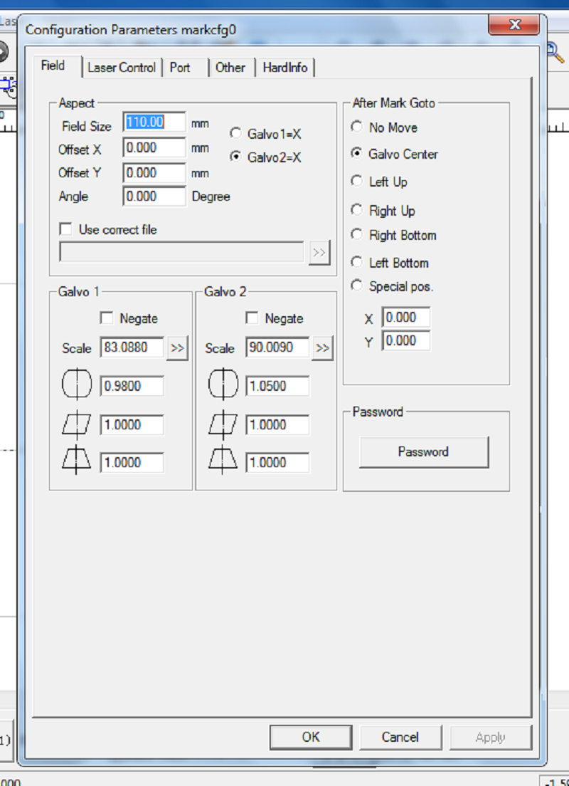
By changing the parameters in the curvature program were kept to a minimum. Also tried to burn holes in the board.

At first there were sloppy edges, then it began to turn out cleaner. As a result, I got a hole on one side clean, on the other not. If you carefully choose the modes, you get beautiful both sides. However, a little later, work on the board was suspended due to the impending problem of joining the two surfaces of the top / bottom board. But I think this work to continue.
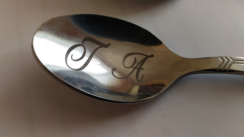
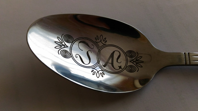
Generation \ embodiment of ideas for creating products under the order
There was an idea to print images on spoons. Were bought teas and tablespoons of stainless steel. I created a vector image for them. I looked for beautiful monogram frames, picked up a few ideas and created my own frame in Corel Draw. In the absence of experience with this program, it took 30-45 minutes to figure out and redraw the image (for a tablespoon).

So passed my first acquaintance with a laser engraver, 2 points out of 3 met. If you have questions or ideas, please write in the comments.
All Articles