Low-voltage tube super regenerative FM receiver without output transformer
Hello.
Note
At the end of the article there are two videos that roughly duplicate the content of the article and demonstrate the operation of the device.
I can assume that many local inhabitants are attracted to electronic devices based on electronic lamps (personally I am pleased with the warmth, pleasant light and monumentality of lamp structures), but at the same time the desire to construct something warm and a lamp with their own hands often breaks about the fear of contacting high voltages. or problems finding specific transformers. And with this article I want to try to help the suffering, i.e. describe the lamp design with low anode voltage, a very simple circuit, common elements and no need for an output transformer. At the same time, this is not just another headphone amplifier or some overdrive for a guitar, but a much more interesting device.
“What is this construction?” - you ask. And my answer is simple: " Superregenerator !".
Superregenerators are a very interesting kind of radio receivers, which is characterized by simplicity of circuits and quite good characteristics, comparable to simple superheterodynamics. Subjects were extremely popular in the middle of the last century (especially in portable electronics) and they are intended primarily for receiving stations with amplitude modulation in the VHF band, but can also receive stations with frequency modulation (i.e., to receive those very ordinary FM stations).
The main element of this type of receivers is a superregenerative detector, which is both a frequency detector and a radio frequency amplifier. This effect is achieved through the use of adjustable positive feedback. I don’t see the point of describing the theory of the process in detail, since “everything is written before us” and is easily mastered through this link .
Further, in this set of books, the emphasis will be placed on the description of the construction of a proven structure, since the schemes found in the literature are often more complicated and require a higher anode voltage, which does not suit us.
I began to search for a circuit that meets the requirements from the book of Comrade Tutorsky, “The Simplest Amateur Transmitters and VHF Receivers” of the sample of 1952. A superregenerator circuit was found there, but I did not find the lamp that I was offered to use, but I didn’t start up the circuit with an analogue, so the searches were continued.
Then this article was found. She already suited me better, but it was attended by a foreign lamp, which is even harder to find. As a result, it was decided to start experiments using a common approximate analogue, namely, a 6n23p lamp, which feels great in VHF and can work with not too large anode voltage.
Taking this scheme as a basis:
And after conducting a series of experiments, the following scheme was formed on a 6n23p lamp:
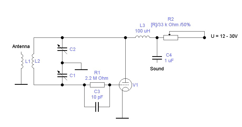
This design works immediately (with proper installation and a live lamp), and produces good results even on ordinary in-ear headphones.
Now let's take a closer look at the elements of the circuit and start with the 6n23p lamp (double triode):
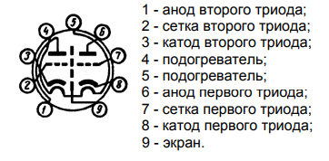
In order to understand the correct positioning of the lamp legs (information for those who have not had cases with lamps before), you need to turn its legs towards you and the key down (sector without legs), then the beautiful view before you will correspond to the picture with the lamp pinout (it works and for most other lamps). As you can see from the picture, there are two triodes in the lamp, but we need only one. You can use any, no difference.
Now let's go on the scheme from left to right. Inductance coils L1 and L2 are best for winding on a common circular base (mandrel); a medical syringe with a diameter of 15 mm is ideal for this, and it is desirable to wind L1 over a cardboard tube that moves along the body of the syringe with little effort than adjusts the coupling between the coils. As an antenna to the terminal L1, you can solder a piece of wire or solder the antenna jack and use something more serious.
L1 and L2 should preferably be wound with a thick wire to increase the quality factor, for example, with 1mm wire and more with a pitch of 2mm (special accuracy is not needed here, so you can not bother with each turn). For L1 you need to wind 2 turns, and for L2 - 4-5 turns.
Next come the C1 and C2 capacitors, which are a two-part variable capacitor (KPI) with an air dielectric, it is an ideal solution for such schemes, and a KPI with a solid dielectric is undesirable. Probably, KPI is the rarest element of this scheme, but it is quite easy to find in any old radio equipment or in flea markets, although it can be seen with two ordinary capacitors (necessarily ceramic), but then you have to adjust using an improvised variometer inductance). Example KPI:
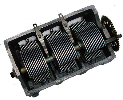
We need only two sections of the CPE and they must be symmetrical, i.e. have the same capacity in any adjustment position. Their common accurate will be the contact of the moving part of the KPI.
This is followed by a quenching chain made on a resistor R1 (2.2 MΩ) and a capacitor C3 (10 pF). Their values can be changed in small limits.
Coil L3 plays the role of an anode choke, i.e. high frequency is not allowed to go further. Any choke (not only on an iron magnetic core) with an inductance of 100–200 μH will do, but it is easier to wind 100–200 turns of a thin copper enameled wire onto a body of a cleaned resistor.
The capacitor C4 serves to separate the DC component at the output of the receiver. Headphones or an amplifier can be connected directly to it. Its capacity can vary within rather large limits. It is desirable that C4 was film or paper, but it will work with ceramic too.
Resistor R3 is a conventional 33kΩ potentiometer, which serves to control the anode voltage, which allows changing the lamp mode. This is necessary for more accurate tuning of the mode for a specific radio station. Can be replaced by a constant resistor, but this is undesirable.
At this elements are over. As you can see the scheme is very simple.
And now a little about the power and installation of the receiver.
Anode power can be safely used from 10V to 30V (it can be more, but it is already a little dangerous to connect low-impedance equipment). The current there is very small and a power supply unit of any power with the required voltage is suitable for power, but it is desirable that it be stabilized and have a minimum of noise.
And another prerequisite is the power of the lamp filament (in the picture with pinout it is designated as heaters), since without it it will not work. Here, currents are needed more (300-400 mA), but the voltage is only 6.3V. It is suitable as alternating 50Hz, and a constant voltage, and it can be from 5 to 7V, but it is better to use canonical 6.3V. Personally, I did not try to use 5V on the heat, but most likely everything will work fine. Glow is served on legs 4 and 5.
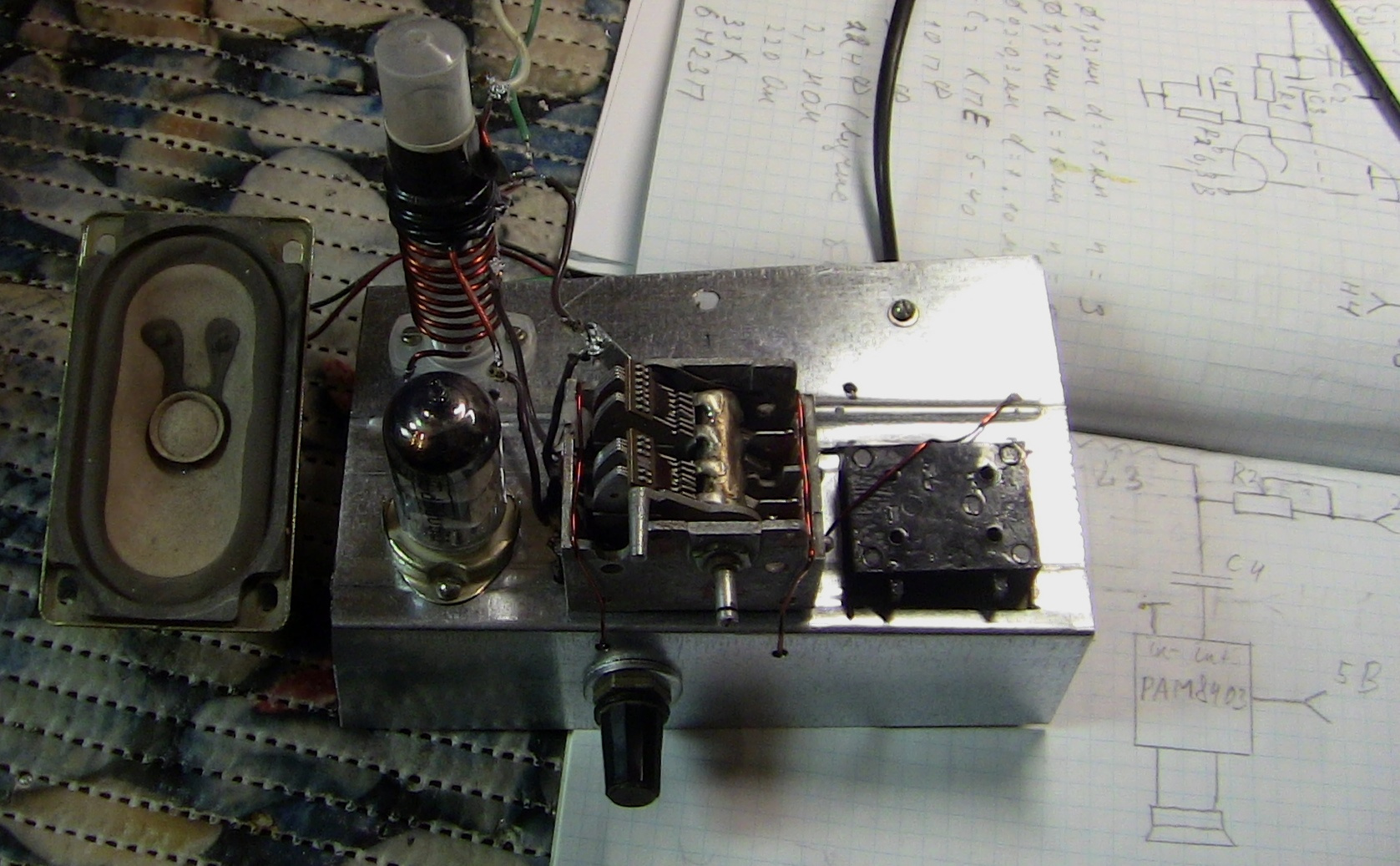
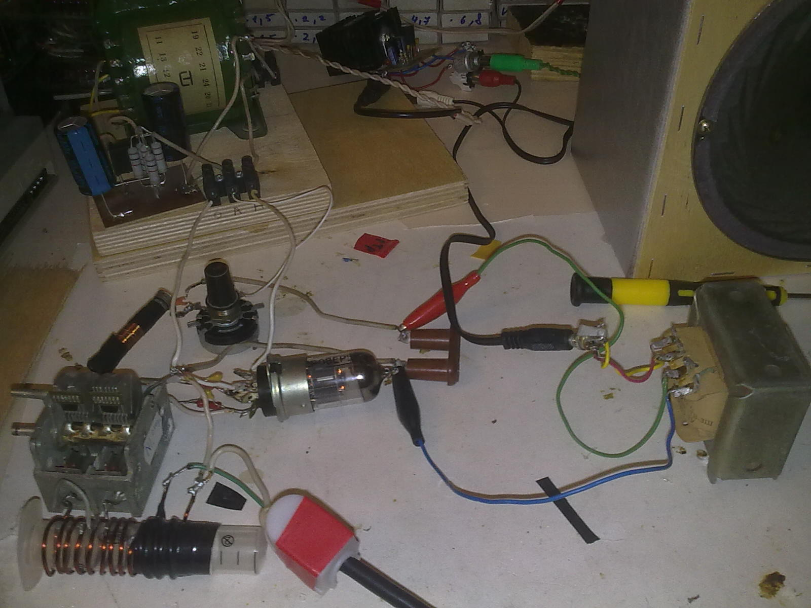
Now about the installation. Ideal is the location of all elements of the circuit in a metal case with the earth connected to it at one point, but it will work even without a case. Since the circuit operates in the VHF band, all connections in the high-frequency part of the circuit should be as short as possible to ensure greater stability and quality of the device. Here is an example of the first prototype:
With this installation, everything worked. But with a metal chassis case is a bit more stable:
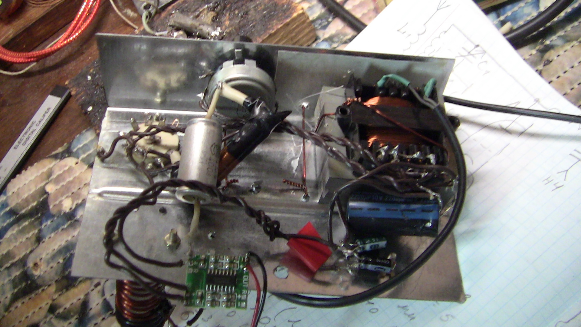
For such circuits, a mounted installation is ideal, since it gives good electrical characteristics and allows you to amend the circuit without much difficulty, which is not so easy and neat with the board. Although my installation can not be called accurate.
Now about the adjustment.
After you are 100% sure that the installation was correct, the voltage was applied and nothing exploded and did not catch fire, which means that the circuit most likely works if the correct element ratings are used. And you will most likely hear noises in the headphones. If you do not overwhelm the stations in all the positions of the CPU, and you are sure that you are receiving broadcast stations on other devices, then try changing the number of turns of the L2 coil, this will change the resonant frequency of the circuit and possibly fall into the desired range. And try turning the variable resistor knob - it can also help. If nothing helps at all, then you can experiment with the antenna. This completes the setup.
At this stage, the most basic has already been said, and the inept narration presented above can be supplemented with the following videos, which illustrate the receiver at different stages of development and demonstrate the quality of its work.
Pure lamp version (at the model level):
Option with the addition of ULF on the IC (already from the chassis):
In the latter version, the luminosity is slightly lost, for the IC is applied. This turned out to be the only solution, since with the anode 20V in the ULF mode, the second triode did not work for me, although there may be a suitable mode, but I could not find it.
The PAM8403 amplifier, which is powered by the linear voltage regulator L7805 (popularly known as the roll, after the name of the Soviet analogue), was used as the ULF.
The plans for the development of this project include the creation of another superregenerator on the 6c6b lamp, but already portative, since it is very tempting to have a tube portable receiver.
Thanks for attention. Ready to answer questions on the topic.
PS: This device generates oscillations during operation and emits them through a receiving antenna, i.e. superregenerator may interfere, consider this.
Sources:
1. Overregeneration
2. Super Regenerative Receiver
3. Documentation for 6n23p lamp
4. Tutorsky "The simplest amateur transmitters and VHF receivers" 1952
All Articles